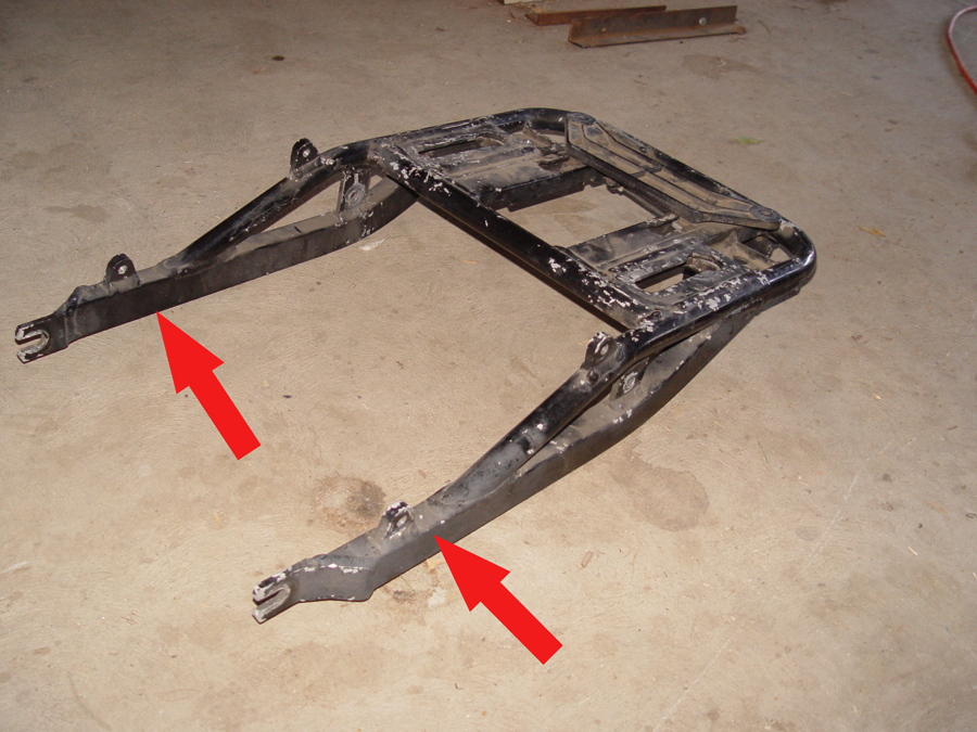
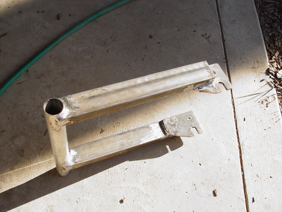
Photo 1 – The cargo case base frame from the donor Kawasaki must be trimmed off to fit the deck lid.
The cargo case from the donor Kawasaki will be mounted on the deck lid and will also serve as a portion of the seat’s back rest. The Kawasaki was equipped with an adjustable sliding base which will be used on the new trike to provide some flexibility in the positioning of the cargo case and allow for a bit of fudge factor when the rest of the seat is constructed later. The slider base is a little too long to fit in the deck lid so the front legs will be cut off approximately at the red arrows. (Photo 1)
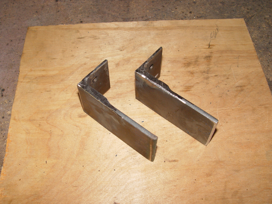
Photo 2 – Mounting brackets to bolt the case to the frame are fabricated from angle stock and flat stock
Rear mounting brackets for attaching the case to the base are made by welding flat stock to angle iron. (Photo 2)
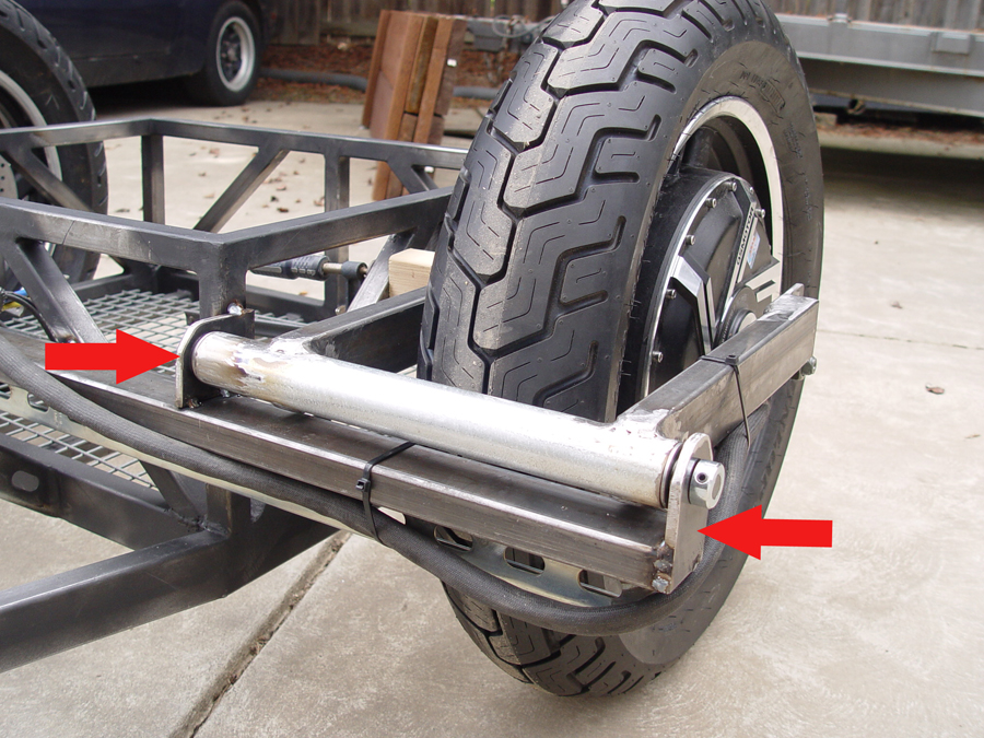
Photo 3 – A view from the underside of the base frame showing the mounting bolt positions
The front of the base frame will bolt directly to a cross member in the deck lid and will not need mounting brackets. Photo 3 shows the underside of the installed slider frame. The rear mounting brackets are indicated by the red arrows and front mounting bolts are indicated by the white arrows. In this photo you can also see the slider release mechanism which allows the case to be moved forward or backward.
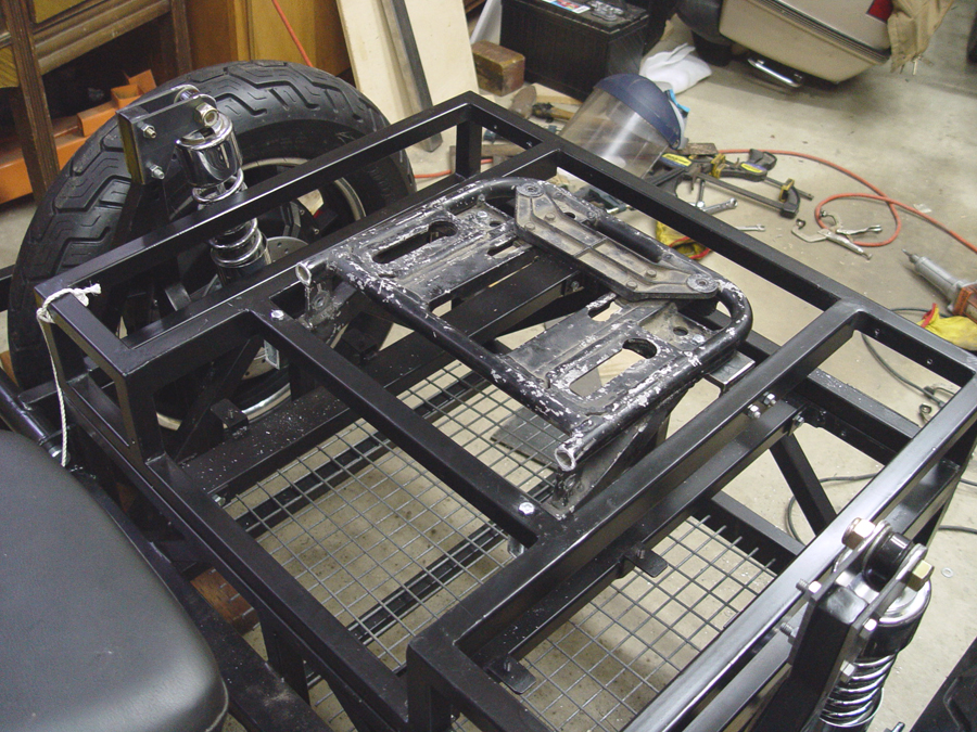
Photo 4 – Top view of the mounted cargo case base
The installed slider frame from the top. (Photo 4)
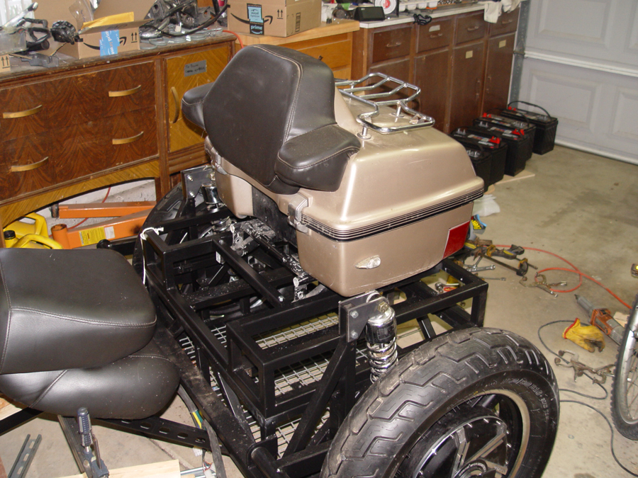
Photo 5 – Side view of cargo case bolted to its base frame
The cargo case can now be bolted to the slider frame. ( photos 5 and 6)
Photo 6 – Rear view of cargo case bolted to its base frame
Photo 7 – The rear deck lid and cargo case in the open position
The deck lid now swings open with the cargo case attached. (Photo 7)
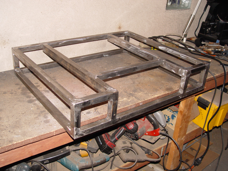
Photo 1 – Rear deck lid is constructed of 1×1 thin wall tubing to match the perimeter of the battery box
Now that the position and height of the controllers and heat sinks have been established, a rear deck lid/battery box cover can be constructed using 1x1x.065 square tubing. (Photo 1) Note that there is an indentation in the front portion of the deck lid. This space is needed so that the seat back will be able to recline into the deck lid.
Photo 2 – Deck lid in place to test for fit
The deck lid is then test fit on the battery box. Note that the controllers are still bolted in place to insure there is proper clearance with the deck lid. Also note the indentation in the front of the lid where the seat back will recline. (Photo 2)
Photo 3 – Rear view of deck lid while checking for fitment
And a view of the deck lid from the rear being checked for proper fit. (Photo 3)
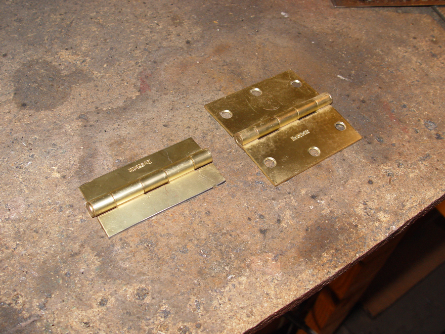
Photo 4 – Steel door hinges are cut down and redrilled for mounting to the 1×1 tubing
The lid is hinged using common steel door hinges. However, the hinges must be cut down and then re-drilled so that the mounting bolt holes will line up properly with the 1×1 tubing of the battery box and deck lid. An original hinge is shown on the right and the cut down version on the left. (Photo 4)
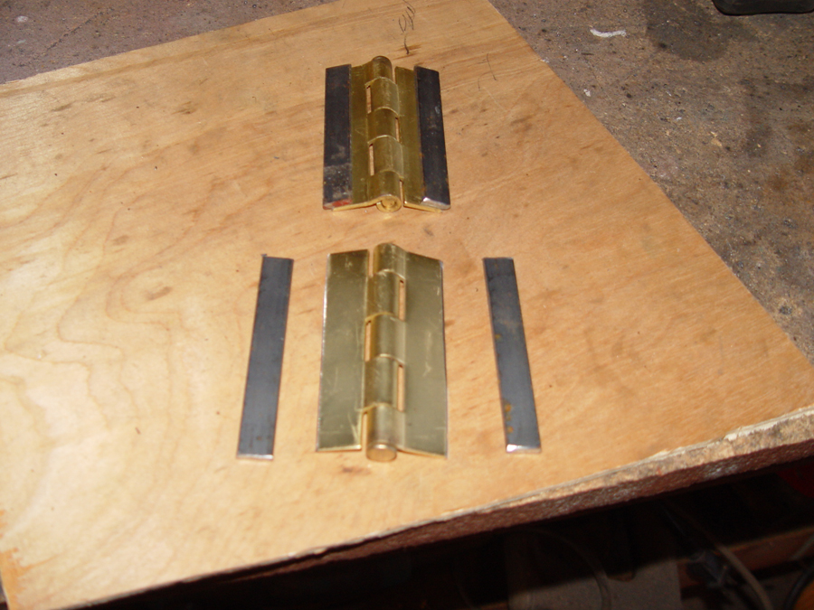
Photo 5 – Steel spacers must be welded to the back sides of the hinges so that they will operate freely
To mount the hinges flat on the surface of the battery box and have them operate properly, spacers are cut from ½ x 1/16″ flat stock and welded to the back side of the steel hinge. (Photo 5)
Photo 6 – The rear hinges (red arrows) bolted in place
Photo 7 – The rear deck lid can now be swung open
Bolt holes are drilled through the hinges and tubing and the hinges are secured to the battery box and deck lid. (See arrows in Photo 6). With the hinges in place the rear deck lid can be swung to the open position. (Photo 7)
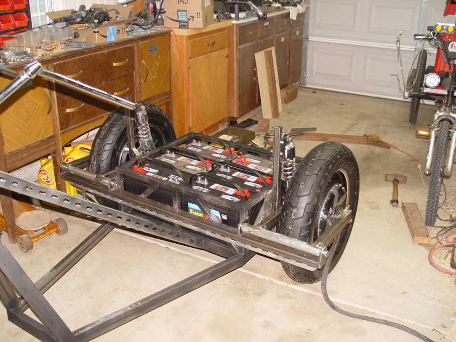
It may seems a bit early in the trike’s progress to by mounting electrical components, but the controllers not only pose a size factor, they must also be positioned so that all the wire harnesses will reach, they can be properly protected from the elements and they will not interfere with any of the other main components of the trike yet to be fabricated. The controllers will be positioned just above the battery box and will be covered by the deck lid which will be constructed later.
Photo 1 – Removable support bars for battery containment and for mounting the heat sinks and controllers
Two support bars are cut from 1x2x.090 rectangular tubing and they are bolted in the battery box so that they are removable (see arrows in Photo 1) The bars serve a dual purpose. First, they lock in the batteries so they can not come loose in the event of an accident. And second, they provide mounting support for the controllers/heat sinks as well as other electrical components which will be located under the rear deck lid.
Photo 2 – brackets for attaching the heat sinks are cut from angle stock
Brackets to mount the heat sinks to the bars are cut from 1 1/4″ angle iron. (Photo 2)
Photo 3 – The brackets are bolted to one of the heat sinks
The brackets are bolted to the pre drilled holes in the heat sink. (Photo 3)
Photo 4 – The heat sink brackets are welded to the outer rail of the battery box and to the inner mounting bar
The heat sink with brackets bolted on is then positioned and clamped in place so that the mounting brackets can be tack welded to the outer perimeter of the battery box and to the inner support bar. (See arrows in Photo 4 showing the heat sink brackets welded in place)
Photo 5 – The heat sink is bolted to the mounting bracketsPhoto 6 – The dual heat sinks bolted in place
The heat sinks are temporarily bolted in place. (Photos 5 and 6)
And the controllers are bolted to the heat sinks. (Photo 7)
With the trike now fully suspended and the basic framework completed, it’s time to sit back and relax with a beverage of choice while mulling over the progress to date and looking over a few photos.
Positioning the rear spring/shock mounts and setting them at the right height can be a daunting task on any scratch built project. During the fabrication process there is no weight on the frame and the mounting points for the top and bottom of the spring/shock are just theoretical points in space. Once the vehicle is completed and under full weight, including the rider, the suspension is going to compress and the vehicle is going to end up at a different ride height than during construction.
The Kawasaki donor had a nice pair of aftermarket Progressive 412 Series, adjustable coil over shocks on the rear which will be used on the new trike. Calculating final ride height and shock compression can be even more of a challenge when using progressive coil springs such as these. With a progressive spring, the spring rate increases as the coil is compressed. My 412-4221 coils, for example, have a spring rate of 140 lbs per inch when fully extended. But they have a spring rate of 200 lbs per inch when fully compressed. And that rate is constantly changing and getting greater over the full 3.52 inches of spring travel. Theoretically the spring rate increases with every incremental increase in compression distance. In actual practice, however, the increase is not perfectly linear. But for estimating ride height one can assume a linear rate increase and get things relatively close.
For this trike I wanted the springs and shocks to be compressed approximately ½ way when the trike is completed and sitting at ride height with the rider aboard. So I calculated an average spring rate over the first half of the spring’s compression (155 lbs per inch for my shocks). I then estimated the total weight of the finished bike and rider AND the estimated weight distribution front and rear. In my case the battery pack will weigh 360 lbs and I estimated 85% of that over the rear wheels and 15% over the front. The rider weight will be 170 lbs distributed 50/50. The frame, seats and all other components were estimated at 150 lbs also distributed 50/50. These calculations put the total weight over the rear wheels at 466 lbs. That weight will be distributed 50/50 between the rear wheels so each spring/shock will support 233 lbs. Dividing that number by the spring rate of 155 lbs per inch indicated each spring would compress approximately 1.5″ with the bike finished and the rider aboard. I wanted the finished bike to sit level at 6″ above the pavement with the rider aboard so I set the frame on 6″ blocks at the front and 7.5″ blocks at the rear. The swing arms, however, are positioned absolutely horizontal to the pavement. With the spring/shock fully extended and the lower shock eye bolted to the swing arm, the position of the upper spring eye can then be identified relative to the frame and future shock mount.
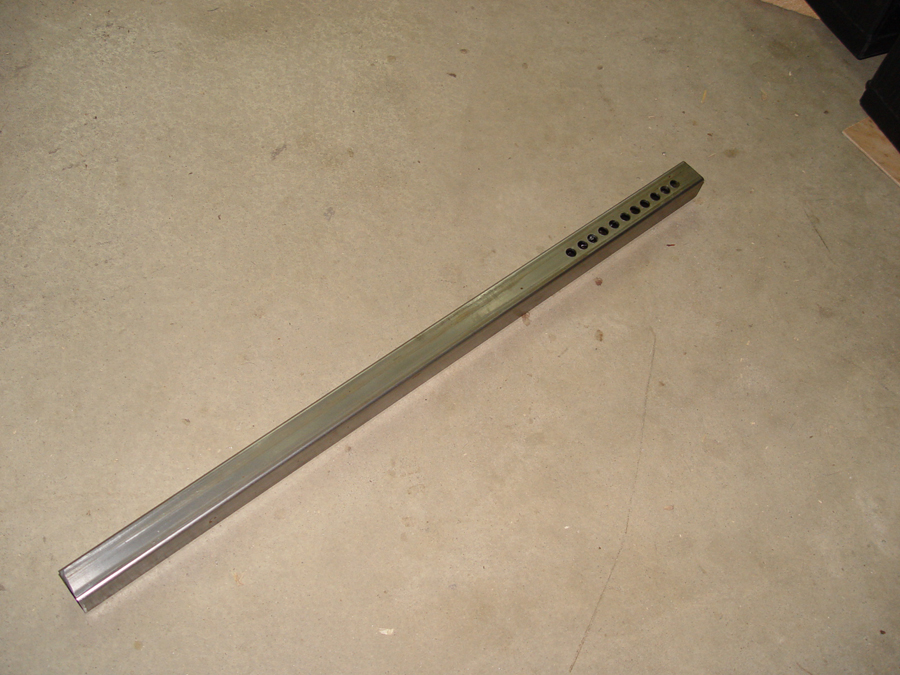
Photo 1 – The shock tower is drilled with 11 positioning holes at the top to allow adjustment of spring and shock height
Since my knowledge of spring physics is quite limited and my mathematical and theoretical calculations always suspect, I allowed myself a fudge factor during fabrication by making my shock towers adjustable. I cut the 1×1 tubing for the towers about 2″ longer than my calculation and then I drilled a series of 11 holes, at half inch intervals, in the tower. (Photo 1) This will allow for adjustment of the upper spring brackets either up or down should the spring position calculations be in error. Once the trike is complete any excess holes at the top of the tower can be cut off and removed.
Photo 2 – 1/4″ flat stock is cut for the upper shock mounting bracketsPhoto 3 – A simple jig is used in a drill press to insure all the mounting holes will line up with the shock tower holes
The upper shock mounts are created by making 3″ x 4″ plates cut from 1/4″ flat stock. (Photo 2) Using a simple jig in the drill press, the four shock mounting plates are drilled out. (Photo 3)
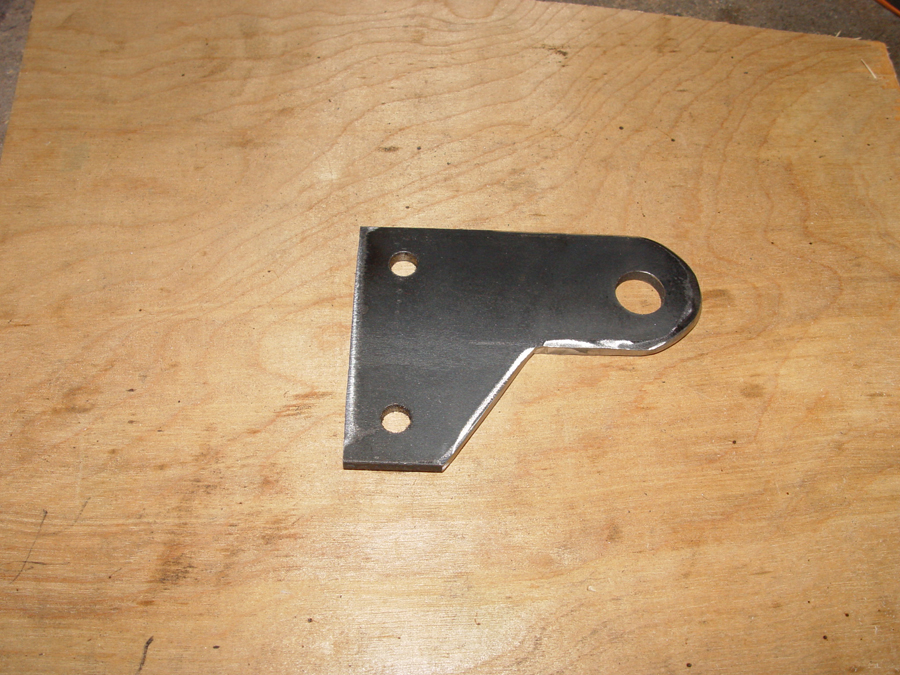
Photo 4 – The large hole is for the shock mounting bolt and the smaller holes are for bolting the bracket to the shock tower
The large single hole in the plate is for the shock eye bolt and the two smaller holes are for bolting the plates to the shock tower. Each plate must also be notched on the bottom to clear the top of the coil/over shock. (Photo 4)
Photo 5 – Shock hanging brackets for both shock towers
A total of four matching plates must be made, two for each shock tower. (Photo 5)
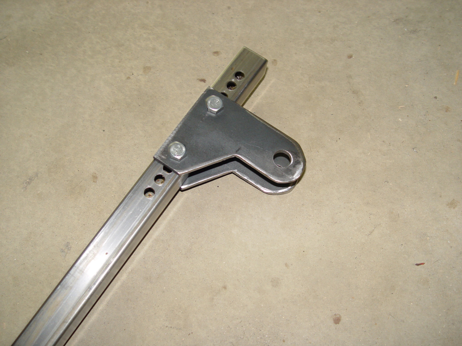
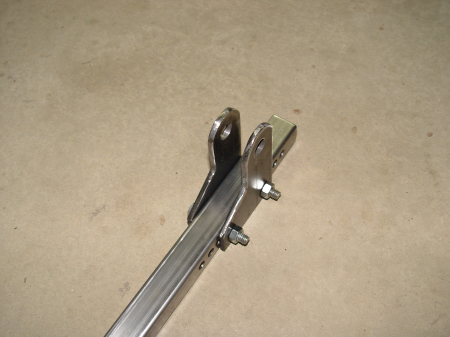
Photo 6 – Shock mounting brackets bolted to the adjustable shock towerPhoto 7 – Shock mounting brackets bolted to the shock tower
The plates are bolted to the spring tower at the estimated height indicated by the spring rate calculations. Note the extra mounting holes for adjusting the ride height. (Photo 6 and 7)
Photo 8 – A grade 8 bolt is inserted through the swing arm and drop out plate to mount the lower end of the spring/shockPhoto – 9 The lower mounting bolt for the spring/shock
The lower spring mount is much easier. It is a 5/8″ grade 8 bolt inserted through the swing arm and drop out plate. (Photo 8 and 9)
Photo 10 – A spacer is needed to align the tower’s upper mounting plates with the lower mounting bolt
To align the top mounting plates with the lower mounting bolt, a spacer cut from 1″ x1 1/2″ rectangular tubing is welded to the shock tower. (See red arrow Photo 10)
Photo 11 – The shock tower is positioned and welded to the frame
The spacer and shock tower will be welded to the frame base and battery box in a vertical position. The tower, however, will be positioned so the upper shock mounting hole on the tower will be a little forward of the lower shock mounting hole on the swing arm. This creates a forward shock angle of approximately 10 degrees. Putting the spring/shock at an angle reduces the effective spring rate. I used an angle similar to what was on the donor Kawasaki. If the ride is too harsh or to spongy once the bike is completed, the Progressive 412 shocks can be adjusted to compensate for the miscalculation. With the swing arm parallel to the ground and the lower spring eye attached to the lower mounting bolt, the shock tower with mounting brackets attached can be positioned on the frame so that the upper spring eye, with the shock fully extended, fits exactly between the holes of the shock tower brackets. If things are “off”, the shock tower brackets can be moved to a higher or lower hole in the tower until everything lines up. When completed the shock tower should be in a vertical position with the bottom of the tower even with the bottom rail of the battery box. Photo 11 shows the shock tower welded in place after the position had been established with the swing arm and spring/shock in place.
Photo 12 – The coil over shocks are bolted in place
With the shock towers welded in place the swing arms are once again installed and the coil over shocks can be bolted in position. (Photo 12)
Photo 13 – The ride height calculations are tested by loading up all the batteriesPhoto 14 – Checking the ride height after installing the battery pack
To see if our calculations, estimates and guesswork for positioning the springs is anywhere near correct the batteries are loaded into the battery box . (Photo 13 and 14) At this point the trike is still about 3/4″ above my design ride height. Once the rest of the framework, electronics, seat, and driver are added, the trike should be within 1/4″ of where I want it to sit. So I may have lucked out with my original calculations and hopefully I won’t have to make any major alterations.
Photo 15 – A final angle brace is welded in to support the upper end of the shock tower
With the upper shock mount position now established and reasonably tested for accuracy, an angle brace (see arrows in Photo 15) is cut and welded to each shock tower to triangulate with the frame and stabilize the towers.
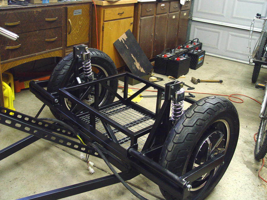
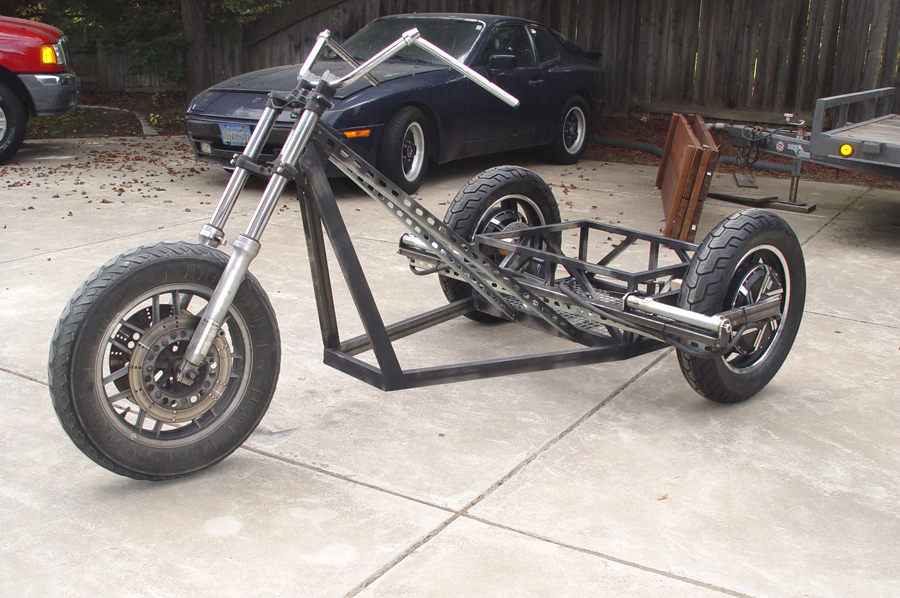
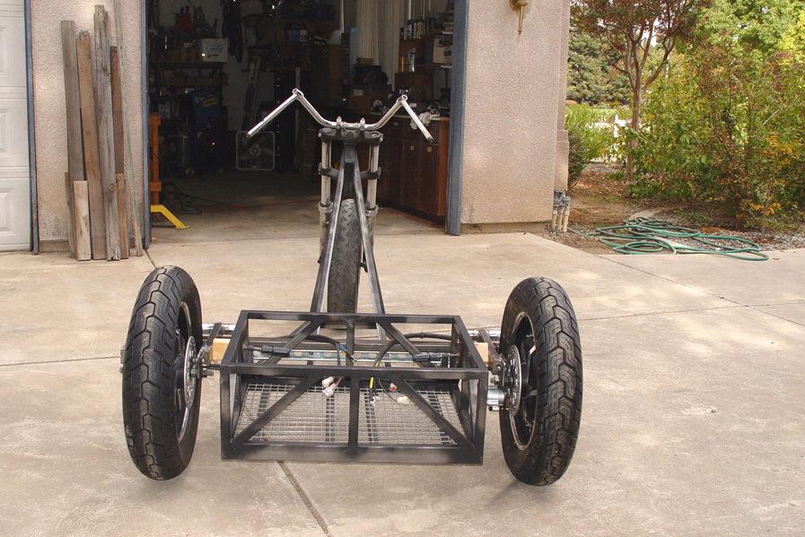
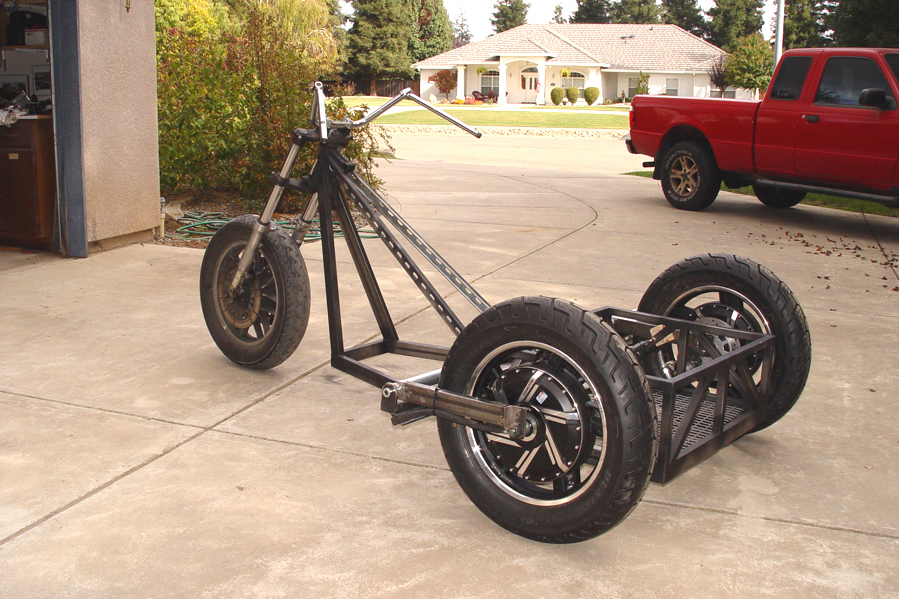
This is a fun day in the progress of every project. The day you can roll the beast out of the garage on its own two, three or four wheels. The chopper trike has no rear suspension yet but with the swing arms clamped in position the bike sees daylight. These photos also begin to hint at how the trike will look in a more finished state.
Photo 1 – Bars are welded to the frame for mounting the swing armsPhoto 2 – Swing arm mounting bars ready for welding
A swing arm mounting bar which spans from wheel to wheel is cut from 1x2x.090 rectangular tubing and clamped to the existing frame of the battery box with the 2″ dimension in the horizontal position. (See upper arrow in Photo 1). A second bar is cut from perforated channel strut and is welded with the long dimension in the vertical position to the underside of the 1×2 tubing (see lower arrow in Photo 1). This prevents the mounting bar from flexing either vertically or horizontally. (Photo 2)
Photo 3 – Bracket plates cut from 1/4″ flat stock with matching 1/2″ holes drilled
Brackets for attaching the swing arm pivot tubes to the mounting bars are cut from 1/4″ flat stock and drilled with ½” holes. There is a size and shape difference between the inside brackets and outside brackets but all four bracket holes must line up in the same position. So as each plate drilled it is marked for proper positioning. (Photo 3)
Photo 4 – Sharp corners are cut off the brackets and ground smooth
Sharp corners are cut off the brackets and then ground to a more rounded shape. (Photo 4)
Photo 5 – Half inch rod is cut to length
Half inch steel rod is cut to length to fit the pivot tube length plus bearings plus brackets plus end collars. (Photo 5)
Photo 6 – Flanged bearing inserted in pivot tube
Flanged bearings with ½” I.D. and 1 3/8″ O.D. are fitted into each end of the pivot tube (see arrow in Photo 6). These particular bearings are rated for a dynamic load of 4900 lbs.
Photo 7 – The swing arm pivot tube brackets are tack welded to the mounting barPhoto 8 – The swing arms welded to the frame
With the swing arm, wheel/tire, and pivot tube square to the frame, the pivot tube brackets (arrows in Photo 7) are clamped and tack welded to the horizontal mounting bar. Once it is certain everything is square and true, the brackets will be permanently welded to the mounting bar. The passenger side swing arm is then welding in place in the same way. The 1/2″ rod is capped on each end with a 1/2″ I.D. collar and set screws. (Photo 8)
Photo – 1 Use heavy card stock to make a pattern for drilling mounting bolt holes
Heavy paper is used to make a template for the caliper mounting bracket and to locate the mounting holes. The bracket is cut from 1/4″ flat stock and the mounting holes drilled. (Photo 1)
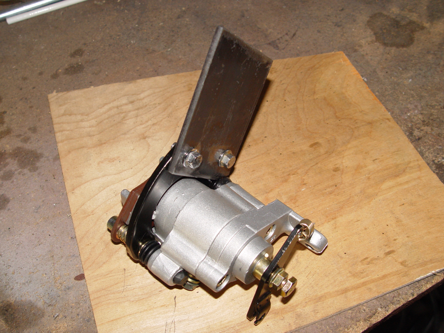
Photo – 2 The caliper is bolted to the mounting bracket
The mounting bracket bolted to the caliper. (Photo 4a)
Photo – 3 Caliper is fitted over the brake disk and the bracket clamped to the swing arm
The wheel and swing arm are positioned and clamped tightly in place. The caliper and bracket are fitted in place with the brake pads slipped over the rotor to insure everything lined up correctly. The bracket (see arrow in Photo 3) is clamped to the swing arm and then tack welded in place. Final welding is done with the swing arm removed from the wheel.
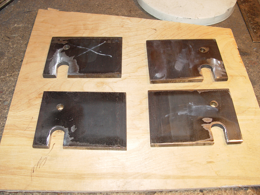
Photo – 1 Quarter inch flat stock drilled for axles and torque plate mounting
The rear wheels will be mounted to the frame using U-shaped swing arms which support both ends of the wheel’s axle shaft. Fabrication of the arms begins by making drop out brackets for the axles. The drop out plates are cut from 1/4 inch steel plate. Two holes are drilled in each plate. The larger whole is drilled to match the axle diameter. The smaller whole is for mounting an axle torque plate. The holes are drilled using a jig on the drill press to insure all four drop out plates match up. (Photo 1) The torque plate is also made from 1/4 inch flat stock and is designed to prevent the torque of the hub motor from twisting or spinning the axle within the slot of the drop out. The QS hub wheels come from the factory with prefabricated torque plates which have a very precise fit on the axle shaft.
Photo 2 – Axle holes are cut open to form drop out slots
The larger axle holes are then cut open to the bottom of the plate so that the axles can be slipped out of the bottom of the plate. This slot must be axle width or slightly larger the entire distance of the slot. (Photo 2)
Photo – 3 Side arms are cut from 1×2 rectangular tubing
The side arms for the swing arms are cut from 1x2x.090 rectangular tubing. The tubing is first cut to TWICE the length for each arm. My arms are going to be 13 3/4″ long but this will vary depending on wheel/tire size and other design differences. Draw a line exactly half the length of the tubing and then drill a hole 1 ½” in diameter in the center of the arm. I used a metal cutting hole saw in the drill press to do this. (Photo 3)
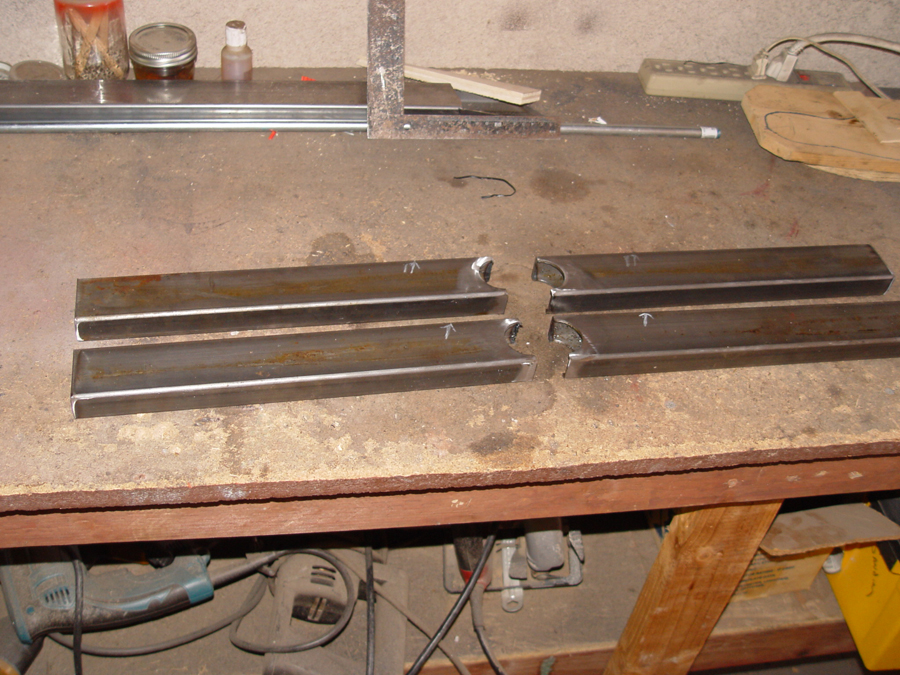
Photo – 4 The tubing is cut exactly in half
Cut the 1×2 tubing exactly in half based on the center line which was drawn earlier. This cut will also be directly in the center of the 1 1/2″ hole. (Photo 4)
Photo – 5 The arms will wrap tightly around 1 1/2″ tubing.
You now have two arms notched to fit quite nicely around 1 ½” O.D. tubing and ready for welding. (Photo 5) The pivot tube for the swing arm is cut from 1 1/2″ O.D. tubing. The length of the pivot tube will vary depending on wheel width and mounting position considerations but for this project the tubes are 13 3/8″ long.
Photo – 6 Drop out blanks are cut to taper up to the side arms
Cut an angle on the bottom of each drop out plate to taper up to the 2″ swing arm. (Photo 6) The drop out plates can then be welded to the side arms.
Photo – 7 Align and clamp the front tube and the side arms for welding
There’s a lot going on in this relatively simple photo so bear with me. The swing arms are being positioned for welding to the front pivot tube. Note the level (black thingy – indicator dial is facing other direction) magnetically held to the disc brake to insure the wheel is vertical. The battery is there simply to help support the wheel in a vertical position. The side arms on each side of the wheel have been tack welded to the drop out plates and the drop out plates have been bolted in their correct position on the axle. The front ends of the two arms are clamped to each other so that they remain even and the pivot tube is fitted into the notch of each arm. The tube will be clamped tightly to the arms just prior to welding. (Photo 7)
Photo – 8 A completed swing armPhoto 9 – Completed swing arm
A completed swing arm with the pivot tube welded to the side arms and the drop out plates welded to the side arms. (Photos 8 and 9)
Photo – 10 A swing arm being mocked up on the frame
The completed swing arm and hub wheel can now be mocked up for attachment to the base frame. (Photo 10)
The batteries and electronic components will be located between the rear wheels and behind the seat. The box will be 24″ x 29″ x11″ (external dimensions) to accommodate the six lead acid batteries. 1x1x.0625 square tubing is cut for the perimeter of the battery box. (Photo 1)
Photo 2 – The tubing is squared up on the base frame and tack welded
The tubing is squared up and welded to the frame base to form the box. (Photo 2)
Photo 3 – Angle bracing is welded in
Additional 1×1 tubing is cut and welded to form the box’s angle bracing. This bracing provides support and strength to the box and to the frame itself. (Photos 3 and 4)
Photo 4 – Another view of the completed battery box