


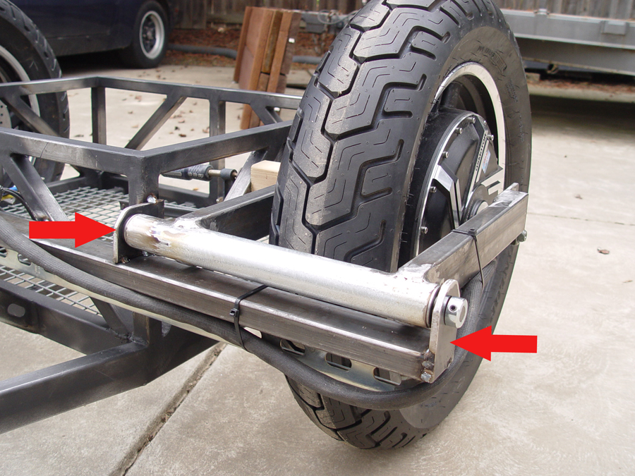
A swing arm mounting bar which spans from wheel to wheel is cut from 1x2x.090 rectangular tubing and clamped to the existing frame of the battery box with the 2″ dimension in the horizontal position. (See upper arrow in Photo 1). A second bar is cut from perforated channel strut and is welded with the long dimension in the vertical position to the underside of the 1×2 tubing (see lower arrow in Photo 1). This prevents the mounting bar from flexing either vertically or horizontally. (Photo 2)

Brackets for attaching the swing arm pivot tubes to the mounting bars are cut from 1/4″ flat stock and drilled with ½” holes. There is a size and shape difference between the inside brackets and outside brackets but all four bracket holes must line up in the same position. So as each plate drilled it is marked for proper positioning. (Photo 3)

Sharp corners are cut off the brackets and then ground to a more rounded shape. (Photo 4)

Half inch steel rod is cut to length to fit the pivot tube length plus bearings plus brackets plus end collars. (Photo 5)

Flanged bearings with ½” I.D. and 1 3/8″ O.D. are fitted into each end of the pivot tube (see arrow in Photo 6). These particular bearings are rated for a dynamic load of 4900 lbs.

With the swing arm, wheel/tire, and pivot tube square to the frame, the pivot tube brackets (arrows in Photo 7) are clamped and tack welded to the horizontal mounting bar. Once it is certain everything is square and true, the brackets will be permanently welded to the mounting bar. The passenger side swing arm is then welding in place in the same way. The 1/2″ rod is capped on each end with a 1/2″ I.D. collar and set screws. (Photo 8)

