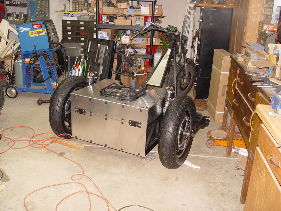
During early road testing the trike pulled to the left under moderate to heavy acceleration. After a good deal of troubleshooting, lasting many many days, it was determined that the Kelly controllers on the trike were programmed at the factory for “speed” mode which did not allow for evenly balanced acceleration when dual hub motors are mounted parallel to one another. The technical service folks at Kelly were very helpful and provided me the necessary software and firmware so I could “re-flash” the controllers to operate in “pure current mode” rather than speed mode. This allowed the two controllers to operate in tandem and balance out the torque to each rear wheel during acceleration. After ironing out a few other minor electrical issue the trike is now up and running. These are photos of the finished project.
Photo 1 – Switches for controlling the 12 volt system are installed in the dash board.
Switches for the 12 volt appliances are installed on the “dashboard” panel. The rectangular switch at the top of the array is a three way switch which “shifts the gears” selecting either forward, neutral or reverse. The four round switches are used to turn on the DC/DC converter, to turn on the 12 volt system itself, to control the daytime running lights (headlight and a tail light) and to control nighttime running lights. (Photo 1)
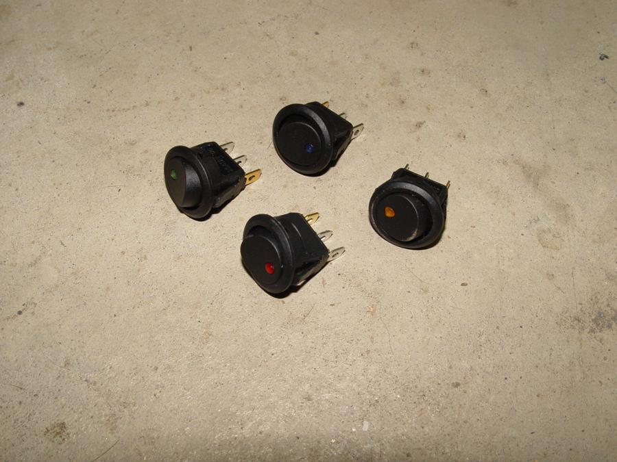
Photo 2 – Rocker switches with LED indicator lights.
The round switches have small LED lights which indicate when the switch is in the ON position. Each switch LED is a different color to assist during night driving. (Photo 2)
Photo 3 – View under the dash board
A view of the switches and wiring from under the dash. (Photo 3)
Photo 4 – Relays located under the dash board
Relays for the turn signals, headlight and running lights are also located under the dash board. (Photo 4)
Photo 5 – Rear of bike showing turn signals, brake lights, tail lights and license plate display light
At the rear of the bike, from bottom to top, are a set of turn signals, a center array which includes the license plate light, brake lights, daytime tail lights and turn signals. Above the center array, in the lower section of the cargo case are the night time tail lights and day/night brake lights. (Photo 5)
Photo 6 – Front end lighting includes headlight and turn signals
At the front of the bike is the headlight which includes internal amber turn signals. To the left and right of the headlight are external turn signals (the pointy arrow like things) (Photo 6)
Also at the front of the bike is my poor man’s “turn signal cancellation unit”. I have turn signals on by 1,000 watt recumbent and I am forever forgetting to turn them off after making a turn. So on this bike I have mounted turn signals on the handlebars which point rearward rather than forward…right at eye level with the rider. (Photo 7) Not only will these turn signals remind me to cancel the unit, they will actually provide a bit more notification of my turn to anyone traveling behind me, particularly at night. Also in this photo is the center mounted Cycle Analyst 3 which provides a wealth of information regarding the electrical system along with controlling many functions such as the throttle, e-brake cut off, cruise control and high temperature safety shut offs.
Photo 8 – Handlebar mounted control module for dimmer, turn signals and horn
I used the Kawasaki donor bike handlebar module for control of the horn, headlight dimmer and turn signals. (Photo 8)
Photo 9 – The main control box for 12 volt and 72 volt systems
The “magic box” showing the 12 volt system wiring along with the 72 volt wiring. Note that a 12 volt battery is installed as well as a dc/dc converter to provide power to the 12 volt system. Once the bike and electrical systems have been fully road tested, I may remove the auxiliary battery and run only off the converter. (Photo 9)
With the 72 volt wiring completed a computer can be connected to the controllers to do some initial programming and to monitor various functions to determine if all the wiring thus far is correct. The monitoring process led to the discovery that my regen throttle controller (see Regen Controller section) was not able to fully engage the thumb throttle and as a result the regeneration was well below full capacity. The regen controller “worked” in the sense that it did, in fact, engage the regen function, it just didn’t move the throttle far enough to reach full regen capacity. Even with various adjustments to the mechanism I was only able to achieve a little more than half the voltage needed to fully engage regeneration.
So the mechanism was dismantled and, as suggested by some helpful readers of this build journal, a simple lever system was created. Fortunately I was able to use the base plate, cable guide and thumb throttle mounting stub from the original design.
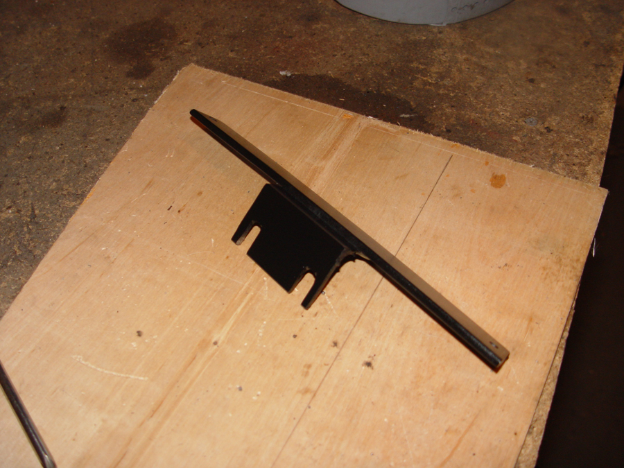
Photo 1 – The lever for the regen controller is cut from 1/8″ flat stock.
The lever is a 4″ long section of ½” wide 1/8″ flat stock. The bottom hole will be the pivot point. The next hole, 1″ up from the pivot, will be used to bolt on the cable from the brake lever. The top hole, 3″ above the pivot, will be used to bolt on the cable to the thumb throttle. (Photo 1) This layout provides a 3:1 ratio. In theory, the 5/8″ of “pull” provided by the brake lever will move the thumb throttle 1 7/8″. In reality, due to slop in the system and minor errors in measurements, the ratio turned out to be slightly less but it was more than enough to move the thumb throttle it’s full 1 ½” travel distance from 0 throttle to full throttle.
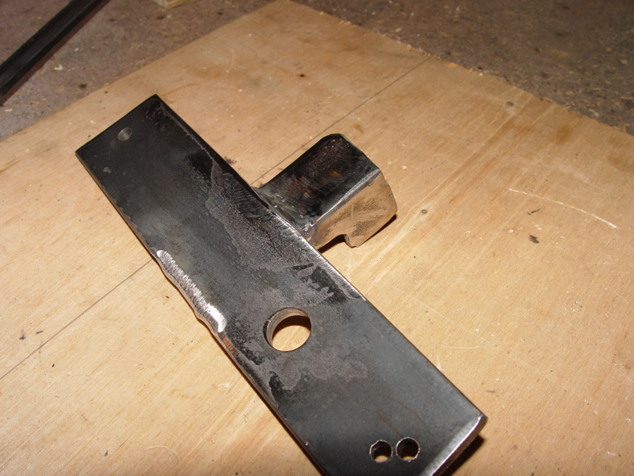
Photo 2 – A quarter inch nut is welded to the pivot hole of the lever.
A 1/4″ nut is welded to the pivot hole of the lever. (Photo 2)
Photo 3 – The lever and nut are threaded onto the mounting plate.
A 1/4″ bolt and “lock nut” are tightened securely to the mounting plate and the nut and lever combination is threaded onto this mounting bolt. The lever nut is threaded just far enough so that it is secure but still rotates freely without becoming tight against the lock nut. (Photo 3) This basically functions as a poor man’s heim joint. The lever easily rotates back and forth while remaining stable and secure on its pivot point.
Photo 4 – The cable guide is bolted to the mounting plate.
The cable guide from my original controller is bolted to the mounting plate so that the cable will line up directly with the lower bolt. The guide was originally part of a discarded hand brake lever. The upper and lower cable bolts on the lever will have small holes drilled through them so that the cables can be inserted in the holes and tightened. Photo 4 shows the lever position when the thumb throttle would be at rest.
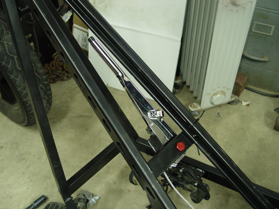
Photo 5 – Lever position when the throttle would be wide open.
Photo 5 shows the lever position when the thumb throttle would be in the wide open position.
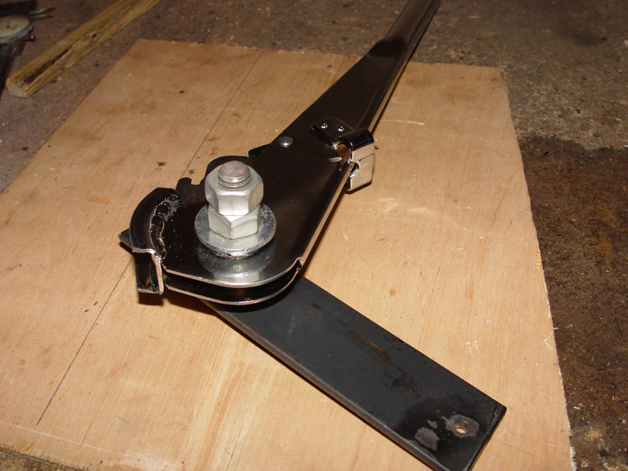
Photo 6 – The completed regen controller mechanism.
The completed mechanism with the thumb throttle, cable guide and lever installed. (Photo 6) Testing with the controller software program indicates this simple lever design is able to provide full throttle power to the controllers and will provide full regeneration capacity. It also pulls easily with the hand brake lever. So thanks to those who provided me with alternative suggestions for the regen mechanism. This design works far better than the earlier version.
The trike will have a 72 Volt (high voltage) wiring system for powering the rear wheels and a 12 Volt (low voltage) wiring system for the peripherals such as headlight, tail lights, turn signals, horn etc. In some instances these two system overlap which will be shown in the progress photos.
Photo 1 – 4 awg welding wire and lugs.
The High Voltage system is powered by six 12 volt deep cycle batteries. The batteries and other high voltage components are wired using 4 awg extra flexible welding cable (all cable and wire sizes are based on recommendations from Kelly Controllers and QS Motors) with 4 awg 3/8″ tubular lug rings. (Photo 1)
Photo 2 – Using lug crimping tool.
A Forney lug crimping tool is used to crimp the lugs to the cable ends. (Photo 2)
Photo 3 – Completed 4 awg wires with lug ends.
A couple completed cables are shown in Photo 3.
Photo 4 – Safety covers for battery terminals are made from discarded milk jugs.
I’ve learned from my smaller electric trike builds that my fumble fingered habits can result in some pretty nasty sparks and blown fuses when a tool or other metal object happens to fall into a battery array and Murphy’s Law asserts itself. To help reduce the chances of accidental shorting across battery terminals “Oops Stoppers” (safety covers) are made from cheap and abundant plastic milk jugs. (Photo 4)
Photo 5 – Holes are punched in the milk carton material for the battery terminal and stud.
The cartons are cut into sections wide enough to cover each battery terminal and its adjoining threaded stud. Two holes are punched out of the plastic so that it fits over the terminal and stud. I used upholstery punches to make the holes nice and round but it could be done with a drill, scissors or exacto knife. The milk carton material can be folded over and pressed by hand to form a “flap” over the top of each lug. (Photo 5)
Photo 6 – A safety cover being installed.
The safety covers are placed over the terminal and stud and then the battery cable is bolted onto the stud when holds the oops stopper in place. (Photo 6)
Photo 7 – Safety covers installed on all the battery terminals.
The battery array with all of the safety covers in place. (Photo 7) These protectors don’t guarantee the elimination of accidents, but they are a cheap and easy preventative measure.
Photo 8 – 1/4″ plexiglass is mounted over the battery pack to provide a surface for mounting the electrical components.
To further help prevent shorting in the battery pack and to provide a non-conductive mounting surface for the major electrical components, a sheet of acrylic plexiglass is mounted over the batteries. The plexiglass is visible as the slightly cloudy surface between the controllers in Photo 8.
Photo 9 – Emergency shut off bracket and shut off modulePhoto 10 – The emergency shut off button mounted to its bracket.
A major safety requirement for any higher voltage electric vehicle is an emergency shut off which is built specifically not to arc and create a major melt down when the battery pack needs to be totally disconnected from the rest of the electrical system. A Holdwell ED250B-1 “Big Red Button” is used for this purpose. The button will be mounted below and just to the right of the rider on the main frame rail and within easy reach. This is also a fairly visible position for emergency crews to find the shut off. A bracket is made from 3/16 flat stock so that the body of the shut off will be surrounded on three sides. (Photos 9 and 10)
Photo 11 – Emergency shut off bracket welded to the framePhoto 12 – The big red shut off button installed
The mounting box is welded in place on the frame. (Photo 11) And the big red button is installed. (Photo 12) The positive cable from the battery array runs directly to the emergency shut off and from the emergency shut off to the contactor.
Photo 13 – An insulated mounting block for the shunt is made using sections of plexiglass epoxied and screwed together
A mounting block for the shunt is made by epoxying together plexiglass sections. This allows the shunt and connectors to be isolated and protected from shorting out on anything metal. (Photo 13)
Photo 14 – Terminal blocks for the primary phase wires from each wheel are made from plexiglass.
Connection terminals for the main wiring from each hub wheel to each controller are fabricated from sections of plexiglass epoxied and screwed together. Each wheel and each controller has three phase wires which will be connected on this terminal block. Each controller will also have a plus and a minus high voltage wire which connect at the terminal block to the plus and minus wires from the battery pack. After these photos were taken, screws were added to the terminal blocks to ensure the epoxy joints remained secure. (Photo 14)
Photo 15 – A wired up terminal block connecting the controller to its hub wheel.
Photo 15 shows the connections made on the terminal block.
The high voltage components installed on the plexiglass mounting panel and wired up. (Photo 16)
To protect the electrical components and wiring for the trike, body panels will be made to enclose the battery and electronics compartment. A body panel will also be created to serve as a “dashboard” for mounting switches and to enclose wiring at the front of the trike. The body panels will be made using lightweight and relatively inexpensive aluminum flashing. Used alone, flashing is too thin and would reveal bumps, bows and other distortions in the metal. So I am using a technique I have used to make dashboards and other panels for some of the hot rods I have built. Each panel has a “core” made from 1/8″ plywood. The aluminum flashing is then cut and glued to the core to form a solid, stable surface. Note that this technique can only be used on flat surfaces or surfaces curved in only one direction. It can not be used for compound curves or compound/complex curves.
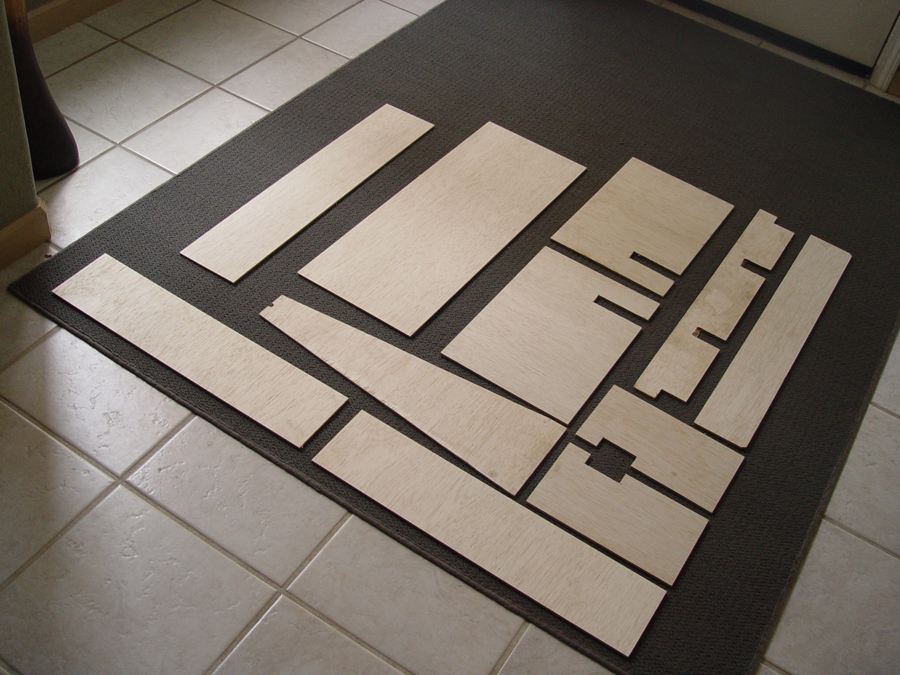
Photo 1 – Cores for each body panel are cut from 1/8″ plywood.
Each panel section core is measured and then cut from 1/8″ plywood. Photo 1 shows all the plywood panel cores for the chopper trike.
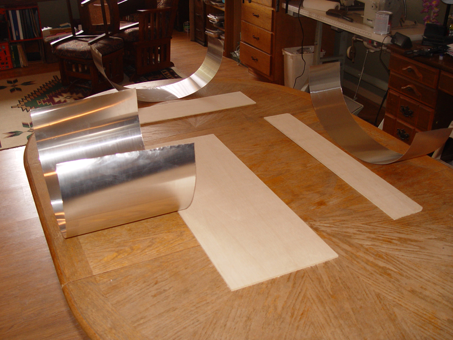
Photo 2 – Aluminum flashing is cut to match the perimeter of the core plus 1/2″ extra along each edge.
Aluminum flashing is cut to the outer shape of each panel with ½” to 5/8″ of extra material on all edges. Do not cut out irregular shapes of the panel at this point. (Photo 2)
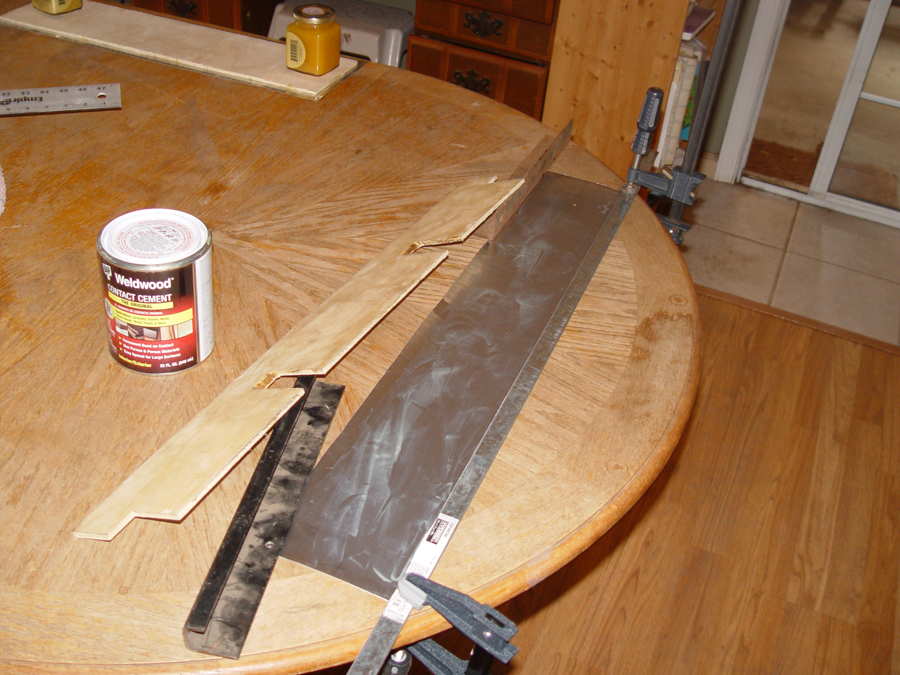
Photo 3 – Apply contact cement and then glue the flashing to the front of the core.
Apply DAP Weldwood contact cement to the front of the plywood and the rear of the aluminum. Dry for the recommended time period and attach the aluminum panel to the plywood panel making sure to leave ½” of flashing extending beyond the plywood on all edges. (Photo 3)
Photo 4 – View of the panel from the plywood core side.
From the plywood side, a simple panel will look something like Photo 4. Note that none of the irregular shapes have been cut out at this point.
Photo 5 – The panel from the flashing side.
On the flashing side the panel will look like Photo 5.
Photo 6 – Detail shot of how to cut an outside corner of the flashing.
Using a good set of tin snips or metal cutting shears cut each outside corner as shown in (Photo 6)
Photo 7 – Inside corners corners at cut as shown and then all edges are glued and folded over the edges of the core.
Inside corners are cut as shown in Photo 7. Once all corners have been cut, apply contact cement to the exposed surfaces and to the back side of the plywood, wait the appropriate time, and then fold the edges of the flashing over the edges of the plywood and press firmly in place on the back side of the plywood.
Photo 8 – The finished panel will look like this from the flashing side.
The finished panel should look something like Photo 8.
Photo 9 shows all of the completed plywood core body panels for the chopper trike.
Photo 10 – The dashboard panel installed.
The “dashboard” panel is installed with machine screws for easy removal. (Photo 10)
Photo 11 – Nylon push rivets are used to install the body panels.
The other body panels are attached using nylon push type fender rivets. (Photo 11) These rivets are most commonly found in automotive application for both interior and exterior fastening. The rivets can be removed once they are in place but they do sometimes break off or become difficult to remove. So if you know a body panel is going to be on and off a number of times it might be better to use a different type of fastener. Also, some may want to choose a different fastener if the do not like the “look” of the rivets.
Photo 12 – Close up view of an installed rivet.
Photo 12 shows a close up of an installed fender rivet.
Photo 13 – The deck lid top panels are riveted in place.
The top panels of the battery box lid are riveted in place. (Photo 13)
Photo 14 – Holes are drilled for running electrical wiring.
Access holes for electrical wiring are cut in the body panels with a hole saw. (Photo 14)
Photo 15 – Grommets are used to protect the wiring where it passes through the body body panel.
Rubber grommets are used to enclose the holes and protect the wiring. (Photo 15)
Photo 16 – A front view of the completed body panels on the battery and electronics compartment.
The front view of the completed body panels. Note that the two openings at the upper left and upper right of the deck lid are purposely left uncovered to allow air flow to help cool the controllers and the battery box. (Photo 16)
Photo 17 shows the completed battery and electronics compartment from the rear.
My Kelly KLS7230S controllers are capable of providing variable regeneration. To alter the amount of regeneration the controllers need a 0-5 volt signal. Most twist and thumb throttles can be used to produce this variable signal. I didn’t like the idea of adding a second twist throttle or a thumb throttle to the handlebars and wanted to utilize a brake lever instead. This brake lever will be mounted on the left side handlebar of the trike and the cable from the lever will run to the thumb throttle mechanism located toward the rear of the trike. Hopefully, this will provide the “feel” of a traditional motorcycle hand brake when the regen is activated.
Unfortunately, the “throw” of the brake lever is not quite long enough for the cable to pull the thumb throttle from the zero position to the full throttle position. As a result, the controllers would not receive a signal for maximum regeneration. To remedy this situation I needed a way to “gear up” the cable so the brake lever movement can provide a longer pull.
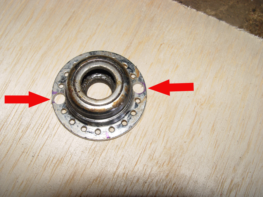
Photo 1 – An old six speed freewheel body will be used to “gear up” cable travel from the brake lever.
To do this I am using a freewheel body from an old six speed cassette stack. (Photo 1). Note that the freewheel body has two grooves (arrows), one larger than the other. By running the incoming brake lever cable around the smaller diameter groove and the outgoing thumb throttle cable around the larger groove, the pull of the brake lever can be multiplied enough to move the thumb throttle lever from its zero position to its 5 volt (maximum) position. The six speed freewheel body is threaded onto the wheel hub allowing it to freely rotate while still being held in the proper position.
Photo 2 – Most of the wheel hub is cut away leaving the threaded disk and the freewheel body.
Only the threaded “cassette” side of the wheel hub is needed, so the balance of the hub is cut off leaving the hub disk and threads as a mounting platform for the freewheel body. (Photo 2)
Photo 3 – The back side of the hub disk.
The hub disk is ground flat on the back side. (Photo 3)
Photo 4 – And old brake lever is cut apart to utilize the guide (arrow) for the incoming cable. A normal brake lever is shown on the right and the cut down guide portion on the left.
To guide the cable from the brake lever onto the groove of the free wheel, an old brake lever handle is cut apart saving the guide (arrow) and a portion of the lever which is drilled for mounting bolts. (Photo 4)
Photo 5 – The threaded disk base for the freewheel body is drilled (arrows) for 1/4″ mounting bolts.
With the freewheel body unscrewed and removed we can see the threaded mount of the hub disk. Two 1/4″ holes are drilled in the hub disk for mounting. (arrows Photo 5)
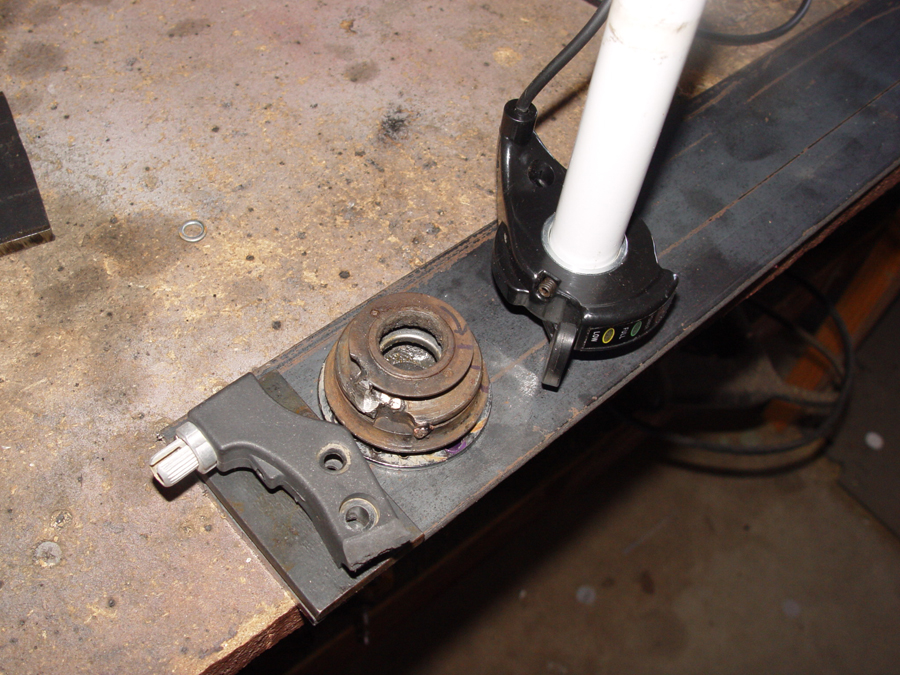
Photo 6 – The guide, freewheel body and thumb throttle being laid out on a mounting plate.
The components are laid out on 3/16 x 3″ wide flat stock. On the left is the “guide”, in the middle is the freewheel body “gear multiplier” and on the right is the thumb throttle. (Photo 6) When everything appears to be in alignment for smooth operation, the mounting points for each component are marked and the flat stock can be cut to the appropriate length and appropriate holes drilled for mounting the guide and the hub disk. The thumb throttle is mounted on a short length of handlebar tubing which is welded to the 3″ flat stock.
Photo 7 – The variable regen components attached to the mounting plate.
The components attached to the base. The thumb pad of the throttle will have a small hole drilled through the center for inserting the cable. (Photo 7)
Photo 8 – Small bridge welds are made over each groove in the freewheel body so that the cables can pass under the weld and then be held with a crimp on the end of the cable.
To secure the end of each cable in the freewheel body groove a “bridge” is welded over the top of each groove. The cable is then inserted into the groove and under the bridge. To insure the weld does not go all the way to the base of the groove, making it impossible to fit the cable under it, a large diameter copper wire is placed in the groove while the bridge is tacked in place. The copper will not bind to the weld and can be pulled out once the weld has cooled. The cable can then be threaded under the bridge, tightened and a stop crimped to the cable. (Photo 8)
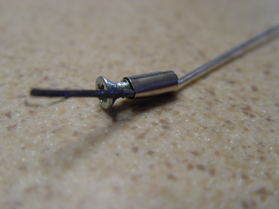
Photo 9 – A cable ferrule and a small screw are used to create a stop for the cable.
Note that the cable from the brake lever to the freewheel body “gear” needs to be adjustable in order to get the cable tight. Instead of crimping on the stop, a cable ferrule is used and a small screw inserted into the open end of the ferrule and tightened securely. (Photo 9)
Photo 10 – An additional spring will be installed to insure the thumb throttle returns to the zero position when the brake lever is disengaged.
The thumb throttle has its own spring to return it to the zero position but to insure the throttle does not hang up due to friction in the cable or gear mechanism, an additional spring (arrow) is attached to the back side of the throttle lever. (Photo 10)
Photo 11 – Variable regen bolted to the trike frame.Photo 12 – Regen components mounted to the trike frame.
The variable regen mechanism is then bolted to the trike frame. (Photos 11 and 12)
The electric trike will require an emergency brake/parking brake primarily to keep the vehicle from rolling when it is parked and shut off. Unlike a car or motorcycle with a mechanical transmission which can keep the vehicle from rolling when it is parked, the electric trike will roll fairly easily if it is on even a minor grade.
The hydraulic brake system I purchased from QS Motors comes with calipers which have a built in emergency and parking brake mechanism and the system also includes the cables and attachment hardware for operating the system. The kit does not, however, include the parking brake handle or a ratcheting mechanism. In addition a bracket must be fabricated for securing the brake cables to the trike’s frame.
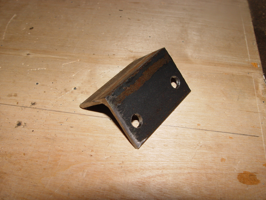
Photo 1 – Angle stock is used to create a mounting bracket to secure the emergency brake cables.
The cable mounting bracket is cut from 1 ½” x 1 ½” angle stock. A hole is drilled to fit the threaded fitting at the end of the brake cable. (Photo 1)
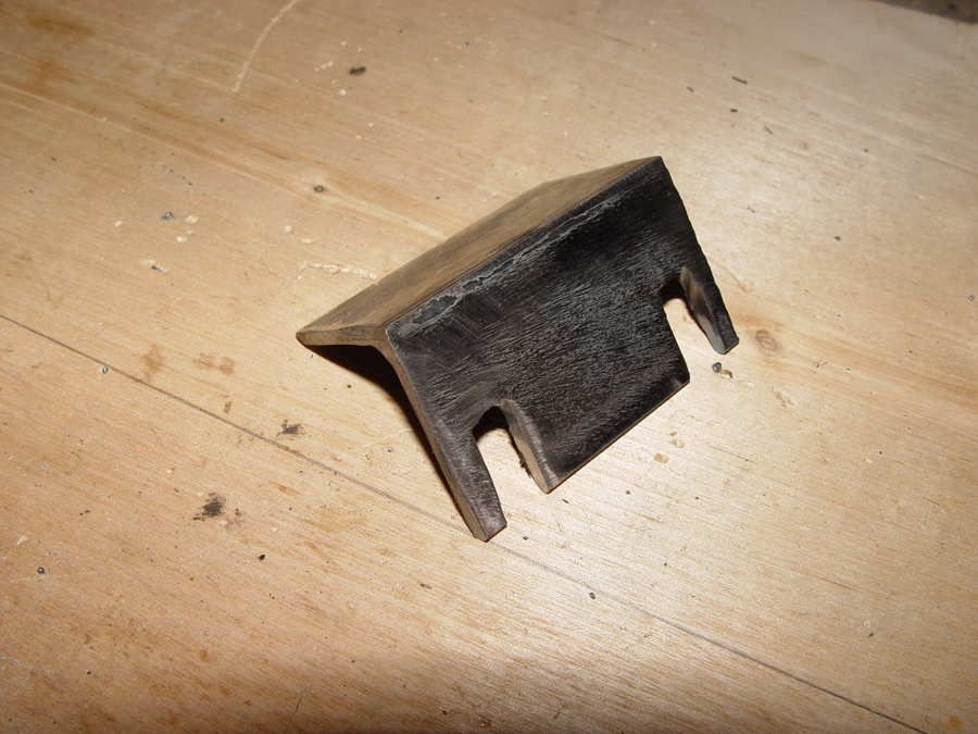
Photo 2 – The holes in the bracket are cut open so the cables can be slipped in place.
The holes in the bracket are opened up to the outer edge so that the brake cables can easily be installed or removed from the bracket. (Photo 2)
Photo – 3 The cable mounting bracket is welded to a cross member which will be bolted to the trike frame.
A cross piece is cut from 3/16″ flat stock so that it can fit the width of the frame. The cable mounting bracket is welded to the cross piece. (Photo 3)
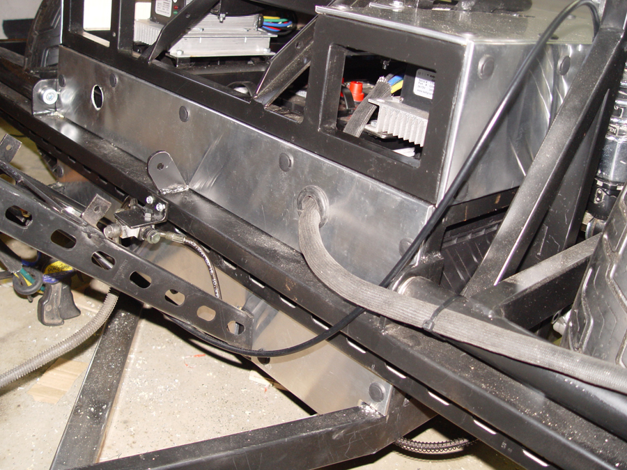
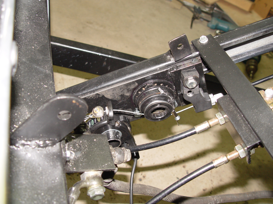
Photo 4 – The cable mounting bracket is bolted to the frame and the cables (arrow) are secured in place.
The cross piece is bolted to the frame and the cables are secured in the mounting bracket. (Photo 4)
Photo 5 – Emergency brake cables secured to the mounting bracket.
Photo 5 shows the underside of the cables bolted into the mounting bracket.
The brake handle and ratcheting mechanism are an aftermarket unit made to fit a Volkswagon Beatle. These brake handles are primarily used in baja bug type builds and can be purchased for $25-$30. (Photo 6)
Photo 7 – A mounting bracket is cut and drilled for the emergency brake handle.
A mounting bracket for the brake handle is cut from 3/16″ flat stock and drilled for the mounting bolt. The holes on each end of the bracket are for bolting it to the trike’s frame. (Photo 7)
Photo 8 – Brake lever bolted to the mounting bracket.
Photo 8 shows the brake handle bolted to the mounting bar.
Photo – 9 This slot (arrow) is used to hold the ratcheting mechanism in position.
The only drawback to using the Baja bug brake handle is that the ratcheting mechanism is not held stationary by the handle itself. Instead, the slot shown at the red arrow in Photo 9 normally hooks to a tab on the Volkswagon driveshaft tunnel and this tab holds the ratcheting mechanism in a fixed position. So a stop must be fabricated to keep the ratchet fixed.
Photo – 10 A “stop” is fabricated from angle iron to fit the slot on the ratcheting mechanism and secure it in place.
The stop is cut from angle iron so that it fits the slot but will not interfere with brake lever as it is engaged or released. (Photo 10)
Photo 11 – The “stop” is welded to the brake lever mounting bracket.
The stop is positioned and then welded to the brake lever mounting bar. (Photo 11)
Photo 12 – The “stop” fits in the ratchet’s slot to secure the ratchet in place.
Photo 12 shows the brake lever bolted to the mounting bar and the ratchet stop (red arrow)
Photo 13 – The brake lever bolted to the frame. Arrow shows the stop and ratcheting mechanism.
Photo 13 shows the entire brake lever mechanism and stop bolted onto the trike’s frame. The red arrow shows the ratchet stop.
Photo 14 – Emergency brake lever in the released position.
Photo 14 shows the brake lever in the released position. In this position it will be tucked under the “dash” of the trike and partially hidden from view once the dash is installed.
Photo 15 shows the brake lever in the engaged position. When engaged the level protrudes out from under the dash and will be easy to spot to remind the rider to release before engaging the motor.
Photo 1 – Stock rear brake pedal assembly from Kawasaki VoyagerPhoto 2 – Pedal side view of Kawasaki brake assembly
The rear brake pedal assembly from the Kawasaki Voyager donor will be used on the new trike. (Photos 1 and 2)
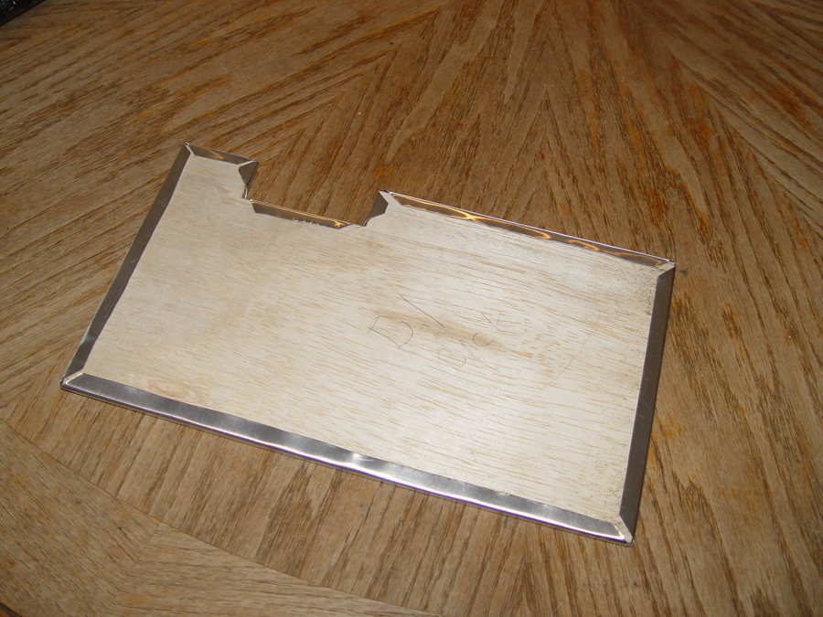
Photo 3 – 3 x 1/4″ flat stock is used to make a mounting plate. Bolt holes are drilled to match the brake pedal assembly.
Quarter inch flat stock is used to create a mounting plate for the brake pedal assembly. (Photo 3)
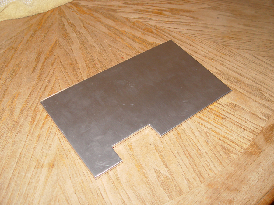
Photo 4 – The fabricated mounting plate is bolted to the brake pedal assembly.
The mounting plate bolted to the brake pedal assembly (Photo 4)
Photo 5 – A wedge is cut from 1/4″ flat stock to offset the brake pedal assembly and allow the pedal arm to clear the frame.
Since the lower frame rail of the trike runs at an angle, the brake pedal bracket must be offset so that the brake pedal arm will clear the frame. A wedge shaped spacer is cut from 1/4″ flat stock to set the brake pedal assembly at the correct angle. (Photo 5)
Photo 6 – The wedge (arrow) is welded to the mounting plate.
The wedge shaped spacer is welded to the mounting plate. (See red arrow in Photo 6)
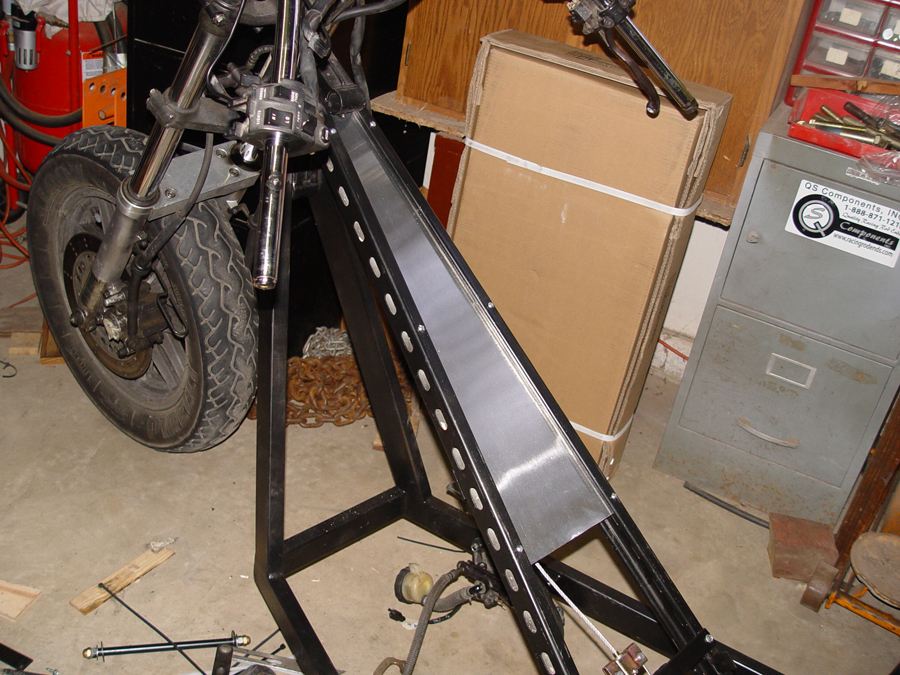
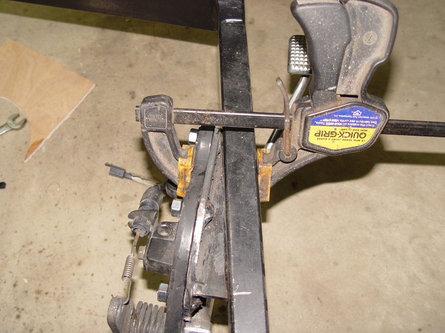
Photo 7 – The pedal assembly is positioned for welding to the frame.Photo 8 – Brake pedal mounting plate welded to the frame.
The entire brake pedal assembly and mounting plate are positioned on the frame to place the pedal where you want it and the assembly is clamped in place for welding. (Photo 7)
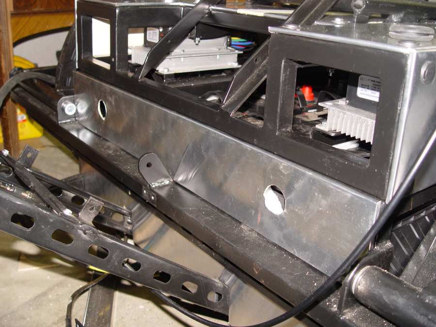
The final mounting position of the mounting plate is too close to the frame to remove the attachment bolts. So the bolts are permanently welded to the mounting plate. Photo 8 shows the completed mounting plate welded to the frame with the pedal assembly removed.
Photo 9 – The Voyager brake pedal assembly mounted to the chopper trike frame.
Photo 9 shows the completed brake pedal assembly bolted to the frame.
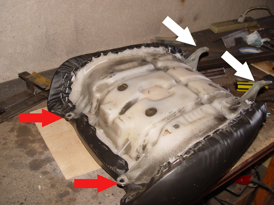
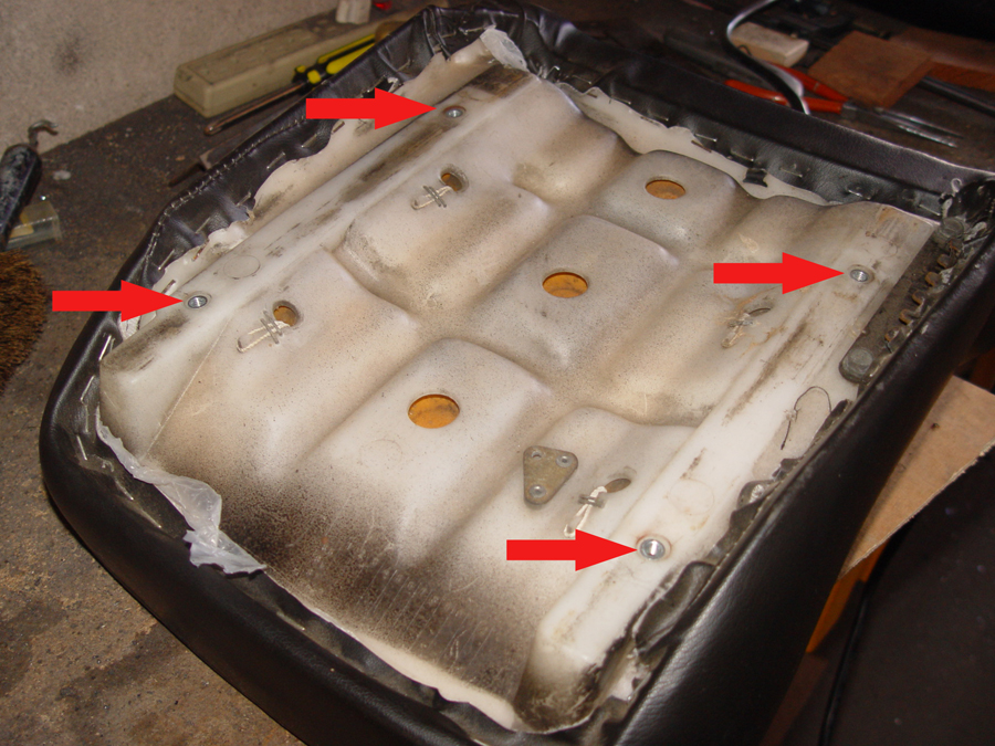
Photo 1 – The underside of the Kawasaki seat showing the original mounting points
The seat is taken directly from the Kawasaki donor bike. Like the seat back, the seat itself also has a formed plastic base. But unlike the seat back it does not have terrific mounting points. The front of the seat originally mounted via a pair of “C” shaped plastic tabs shown with the white arrows in Photo 1. The rear of the seat was held in place with a pair of plastic mounting tabs shown with the red arrows in Photo 1 Unfortunately the rear mounting tabs are not very strong and are meant only to keep the seat from moving around and not meant to be load bearing. Instead, all of the weight on the seat was originally transferred to the formed plastic which rested directly on the frame of the Kawasaki. As a result, the two plastic attachment tabs at the rear of the seat can not bear much weight.
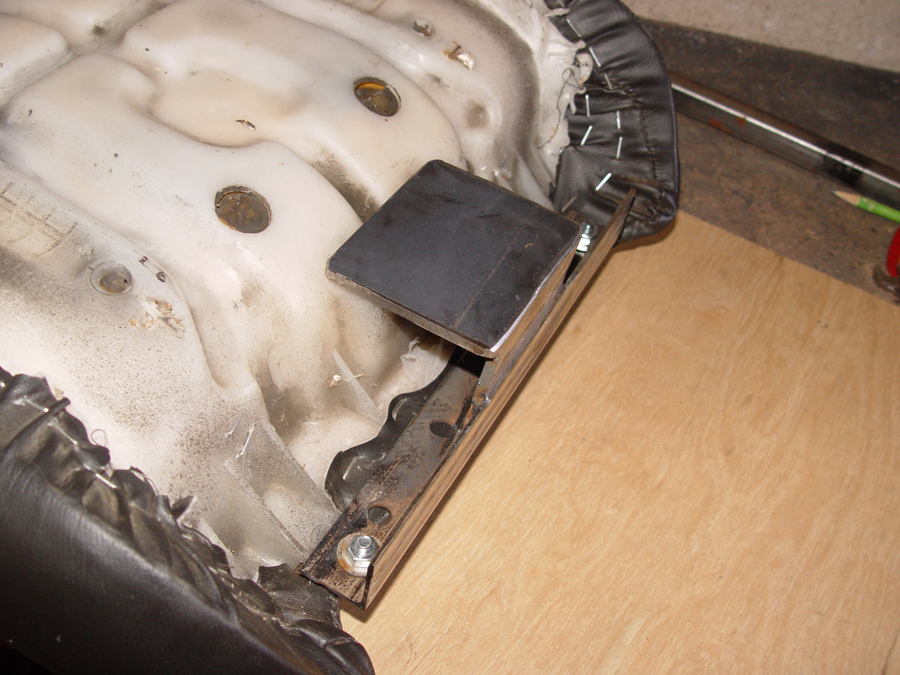
Photo 2 – The underside of the Kawasaki seat showing the strong, solid ledge formed into the plastic
Fortunately, there is a strong, flat area molded into the back edge of the seat (see red arrow in Photo 2). This area is strong enough to support the back end of the seat while the front of the seat will rest on the frame of the trike itself. The front “C” clips will still be used to keep the front of the seat held in place but will not be load bearing.
Photo 3 – A rear mounting bracket is made to rest on the solid shelf at the rear of the seat and bolts to the original mounting holes on the seat to prevent it from moving
A support bracket at the rear of the seat is made using a length of angle iron which is bolted to the two plastic mounting tabs. Quarter inch flat stock is then used to make a mounting pad which rests on the solid flat portion of the formed plastic. The flat stock is positioned and welded to the angle iron cross piece. (Photo 3)
Photo 4 – The seat rear mounting bracket removed from the bike
This is what the rear mount and seat support looks like when it is welded together and removed from the seat. (Photo 4)
Photo 5 – Two support posts are welded to the rear seat bracket
With the rear bracket back on the seat, two support posts are cut from 3/4 x 3/4 rectangular tubing and bolted to the support bracket. (Photo 5)
Photo 6 – Tabs are welded to the bike frame and the posts are bolted in place
The seat is then flipped over and the support posts are bolted to small tabs welded to the frame of the trike. (Photo 6) Additional holes can be drilled in the support post to raise or lower the rear of the seat to get a more comfortable angle if necessary.
Photo 7 – The front of the seat is mounted using the original Kawasaki “C” clips so that the angle of the seat can be adjusted if necessary
The front of the seat is held in place using a ½” steel rod which passes through the trike frame (enclosed in a steel tube) and the two “C” clips on either side of the seat. The inside of the plastic “C” clip fits snugly against the trike frame preventing the seat from moving left of right and the clip and steel rod prevent the seat from moving upwards. (Photo 7) The rod and “C” clip act as a hinge so that the angle of the seat can be adjusted by moving the rear seat bracket up or down.
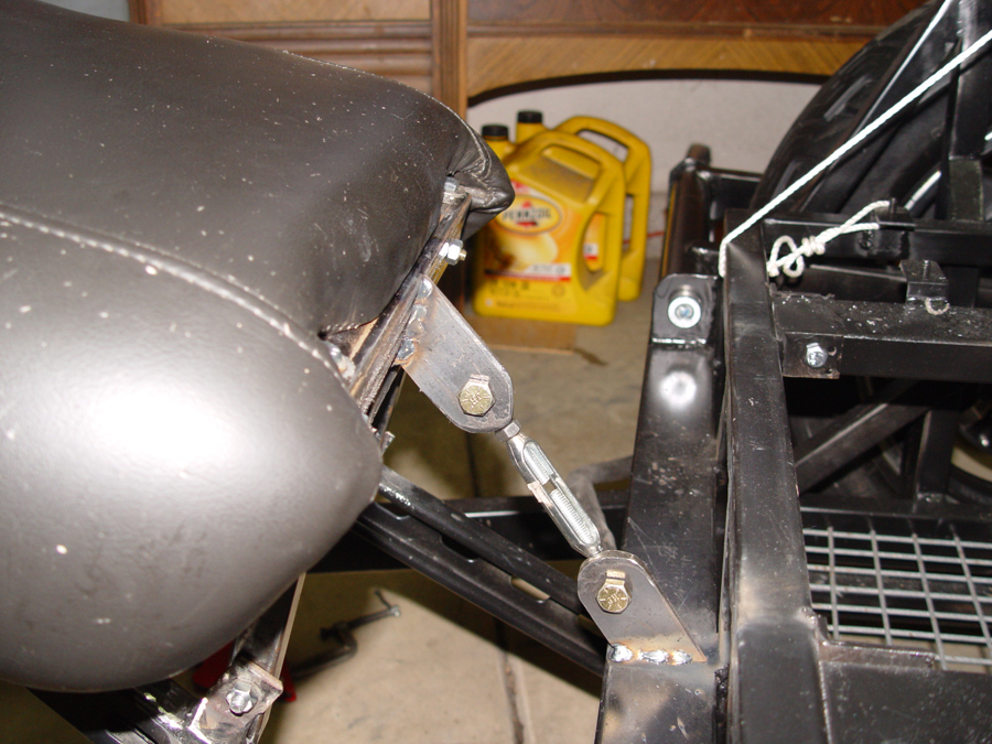
Photo 8 – An adjustable turnbuckle is used to prevent the seat from moving rearward
While the seat can not move forward because of the steel rod and “C” clip, it could possible collapse toward the rear of the trike if the bolts on the support posts were to loosen slightly. To prevent any rearward movement of the seat, brackets are welded to the rear seat support and the center of the trike frame and an adjustable turnbuckle is bolted to the brackets. (Photo 8)
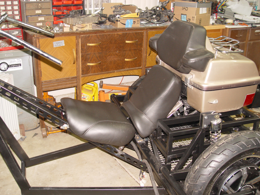
The completed seat with adjustable back rest. (Photo 9)
Photo 1 – Arrows indicated mounting nuts fused into the plastic seat back. These will be used for attaching the mounting hardware
I am using the passenger seat from the Kawasaki donor as a seat back/back rest on the new trike. The underside of the seat back is formed plastic with four threaded bolt receivers fused into the plastic. These will be used for attaching to an adjustable bracket which will then be mounted to the frame of the trike. (See arrows Photo 1)
Photo 2 – Mounting brackets and arms are cut from angle iron
Four mounting tabs are cut from angle iron and drilled for bolts and two mounting rails are also cut from angle iron and drilled for bolts. (Photo 2)
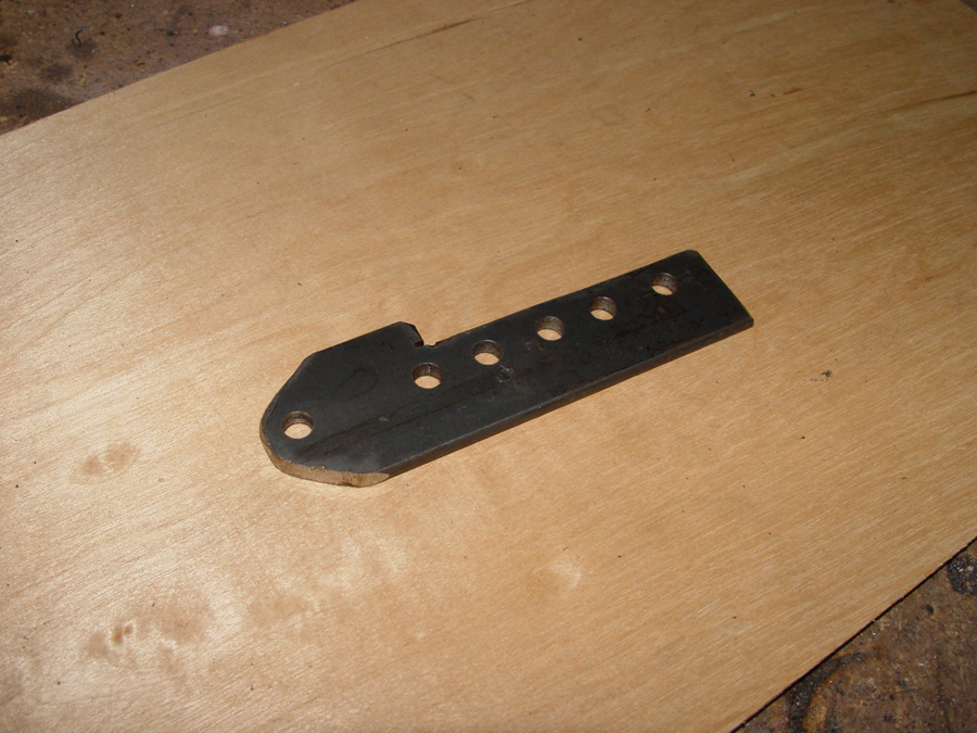
Photo 3 – The adjustment arm will allow for changing the angle of the seat back
An adjuster arm is cut from 1/4″ flat stock and drilled with a series of adjustment holes. This will allow the angle of the seat back to be altered for the most comfortable riding position. (Photo 3)
Photo 4 – The adjustable seat mounting hardware bolted to the seat backPhoto 5 – The adjustable seat back hardware bolted in place
The tabs, rails and adjustment arms are bolted to the bottom of the seat back. (Photos 4 and 5) The bottom of the seat back rail (on the right in Photo 4) will remain in a fixed location but can be pivoted around its attachment bolt. By selecting different mounting holes the top of the rail (on the left in Photo 4) can be adjusted either forward or backward to provide optimal back support and a comfortable riding angle.
Photo 6 – The side rails of the mounting mechanism are welded to the rear deck lid
The mounting assembly is taken apart and the two side rails (see red arrows in Photo 6) are positioned and welded to the frame of the rear deck lid.
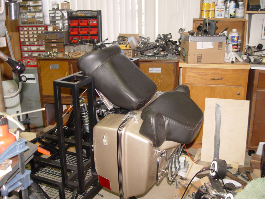
Photo 7 – The seat back is mounted to the rear deck lid
The mounting hardware can then be reassembled and the seat back bolted in place and adjusted to the desired angle. (Photos 7 and 8)
Photo 8 – The seat back mounted to the deck lid
Photo 9 – The cargo case can be opened from the rearPhoto 10 – The deck lid can be swung open with the seat back and cargo case in place
The cargo case now opens normally from the rear (Photo 9) while the deck lid, cargo case, and seat back can be swung up and open for access to the battery pack and electronics. (Photo 10)