
Positioning the rear spring/shock mounts and setting them at the right height can be a daunting task on any scratch built project. During the fabrication process there is no weight on the frame and the mounting points for the top and bottom of the spring/shock are just theoretical points in space. Once the vehicle is completed and under full weight, including the rider, the suspension is going to compress and the vehicle is going to end up at a different ride height than during construction.
The Kawasaki donor had a nice pair of aftermarket Progressive 412 Series, adjustable coil over shocks on the rear which will be used on the new trike. Calculating final ride height and shock compression can be even more of a challenge when using progressive coil springs such as these. With a progressive spring, the spring rate increases as the coil is compressed. My 412-4221 coils, for example, have a spring rate of 140 lbs per inch when fully extended. But they have a spring rate of 200 lbs per inch when fully compressed. And that rate is constantly changing and getting greater over the full 3.52 inches of spring travel. Theoretically the spring rate increases with every incremental increase in compression distance. In actual practice, however, the increase is not perfectly linear. But for estimating ride height one can assume a linear rate increase and get things relatively close.
For this trike I wanted the springs and shocks to be compressed approximately ½ way when the trike is completed and sitting at ride height with the rider aboard. So I calculated an average spring rate over the first half of the spring’s compression (155 lbs per inch for my shocks). I then estimated the total weight of the finished bike and rider AND the estimated weight distribution front and rear. In my case the battery pack will weigh 360 lbs and I estimated 85% of that over the rear wheels and 15% over the front. The rider weight will be 170 lbs distributed 50/50. The frame, seats and all other components were estimated at 150 lbs also distributed 50/50. These calculations put the total weight over the rear wheels at 466 lbs. That weight will be distributed 50/50 between the rear wheels so each spring/shock will support 233 lbs. Dividing that number by the spring rate of 155 lbs per inch indicated each spring would compress approximately 1.5″ with the bike finished and the rider aboard. I wanted the finished bike to sit level at 6″ above the pavement with the rider aboard so I set the frame on 6″ blocks at the front and 7.5″ blocks at the rear. The swing arms, however, are positioned absolutely horizontal to the pavement. With the spring/shock fully extended and the lower shock eye bolted to the swing arm, the position of the upper spring eye can then be identified relative to the frame and future shock mount.
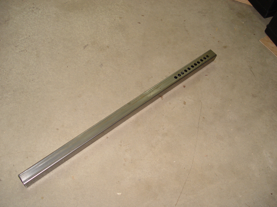
Since my knowledge of spring physics is quite limited and my mathematical and theoretical calculations always suspect, I allowed myself a fudge factor during fabrication by making my shock towers adjustable. I cut the 1×1 tubing for the towers about 2″ longer than my calculation and then I drilled a series of 11 holes, at half inch intervals, in the tower. (Photo 1) This will allow for adjustment of the upper spring brackets either up or down should the spring position calculations be in error. Once the trike is complete any excess holes at the top of the tower can be cut off and removed.


The upper shock mounts are created by making 3″ x 4″ plates cut from 1/4″ flat stock. (Photo 2) Using a simple jig in the drill press, the four shock mounting plates are drilled out. (Photo 3)
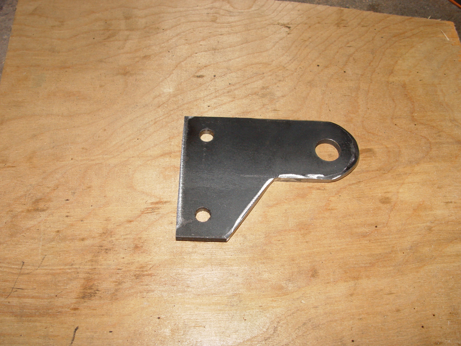
The large single hole in the plate is for the shock eye bolt and the two smaller holes are for bolting the plates to the shock tower. Each plate must also be notched on the bottom to clear the top of the coil/over shock. (Photo 4)

A total of four matching plates must be made, two for each shock tower. (Photo 5)
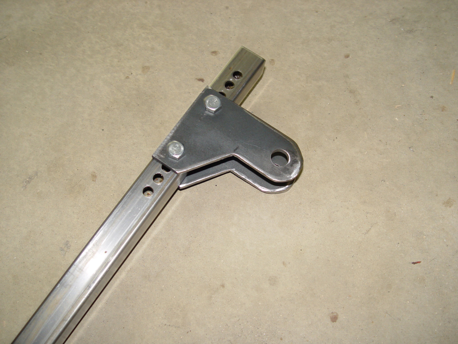
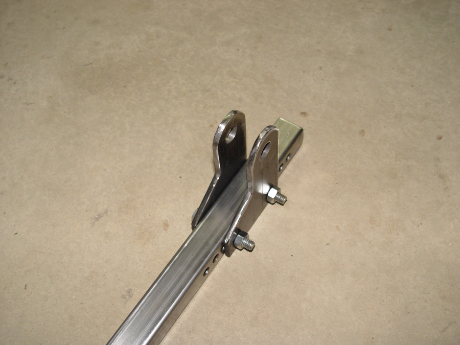
The plates are bolted to the spring tower at the estimated height indicated by the spring rate calculations. Note the extra mounting holes for adjusting the ride height. (Photo 6 and 7)


The lower spring mount is much easier. It is a 5/8″ grade 8 bolt inserted through the swing arm and drop out plate. (Photo 8 and 9)

To align the top mounting plates with the lower mounting bolt, a spacer cut from 1″ x1 1/2″ rectangular tubing is welded to the shock tower. (See red arrow Photo 10)

The spacer and shock tower will be welded to the frame base and battery box in a vertical position. The tower, however, will be positioned so the upper shock mounting hole on the tower will be a little forward of the lower shock mounting hole on the swing arm. This creates a forward shock angle of approximately 10 degrees. Putting the spring/shock at an angle reduces the effective spring rate. I used an angle similar to what was on the donor Kawasaki. If the ride is too harsh or to spongy once the bike is completed, the Progressive 412 shocks can be adjusted to compensate for the miscalculation. With the swing arm parallel to the ground and the lower spring eye attached to the lower mounting bolt, the shock tower with mounting brackets attached can be positioned on the frame so that the upper spring eye, with the shock fully extended, fits exactly between the holes of the shock tower brackets. If things are “off”, the shock tower brackets can be moved to a higher or lower hole in the tower until everything lines up. When completed the shock tower should be in a vertical position with the bottom of the tower even with the bottom rail of the battery box. Photo 11 shows the shock tower welded in place after the position had been established with the swing arm and spring/shock in place.

With the shock towers welded in place the swing arms are once again installed and the coil over shocks can be bolted in position. (Photo 12)
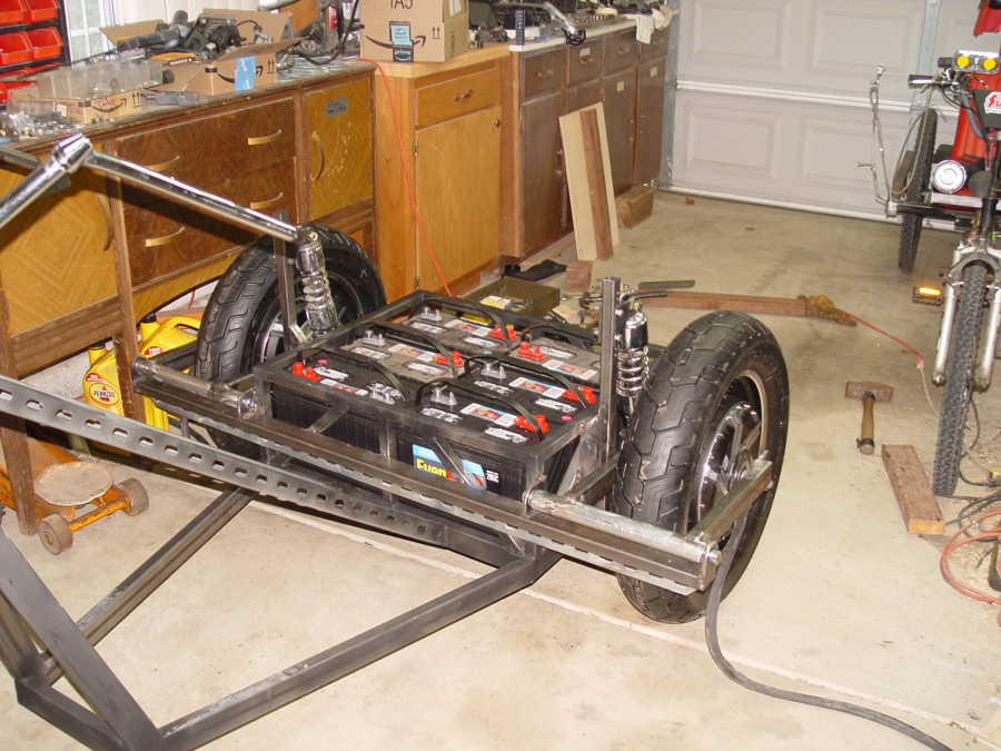

To see if our calculations, estimates and guesswork for positioning the springs is anywhere near correct the batteries are loaded into the battery box . (Photo 13 and 14) At this point the trike is still about 3/4″ above my design ride height. Once the rest of the framework, electronics, seat, and driver are added, the trike should be within 1/4″ of where I want it to sit. So I may have lucked out with my original calculations and hopefully I won’t have to make any major alterations.

With the upper shock mount position now established and reasonably tested for accuracy, an angle brace (see arrows in Photo 15) is cut and welded to each shock tower to triangulate with the frame and stabilize the towers.

