All posts by admin

Front Fork

Photo 1 – Setting front fork angle

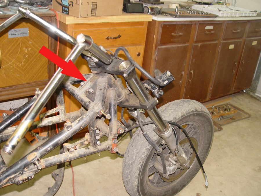
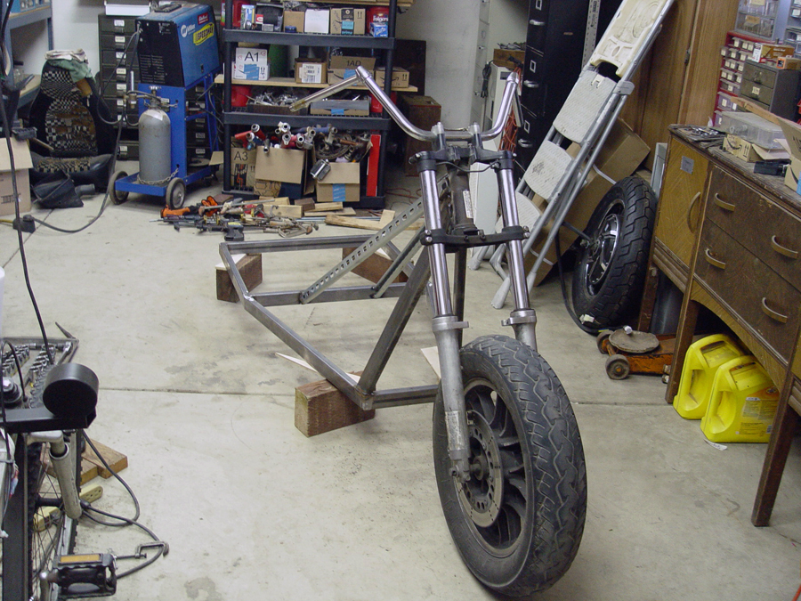
The front fork will be set at a 28 degree angle (matching the angle of the original voyager) and held in place using two upright supports and two angled supports.   While being set up for welding, the fork is held in position on an adjustable tripod (the orange legs in Photo 1) to keep it at the correct rake angle.  Note the lengths of 1×2 tubing (see arrows) which have been clamped to the side rails of the base frame, squared, and extended forward. These rail extensions act as guides for centering the front wheel and fork with the frame base. (Photo 1)

Photo 2 – Centering front wheel and fork

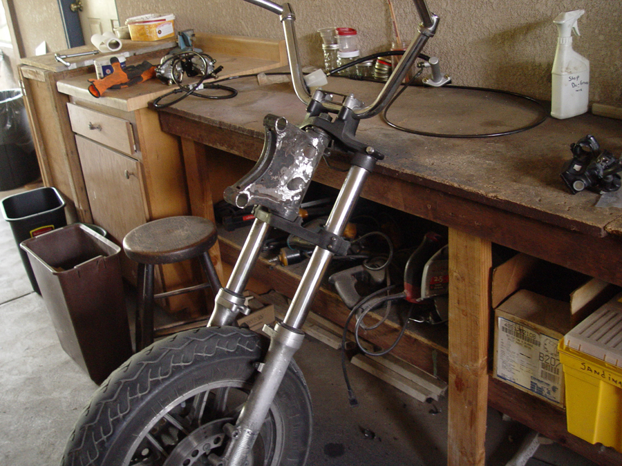
Photo 2 is a front shot of the fork being positioned. Note the extended side rails to the left and right of the front wheel used for determining the center position of the wheel.


Photo 3 – Close up of stops (red) and centering pin (white) which limit wheel turn radius
Photo 4 – Shims clamped in place to center front wheel, steering head and connection box

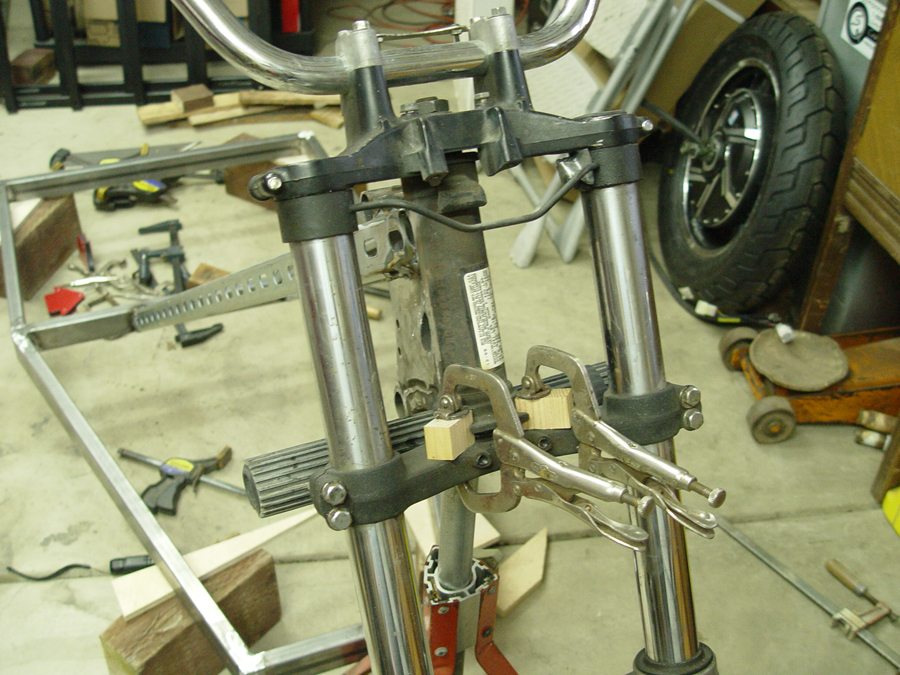
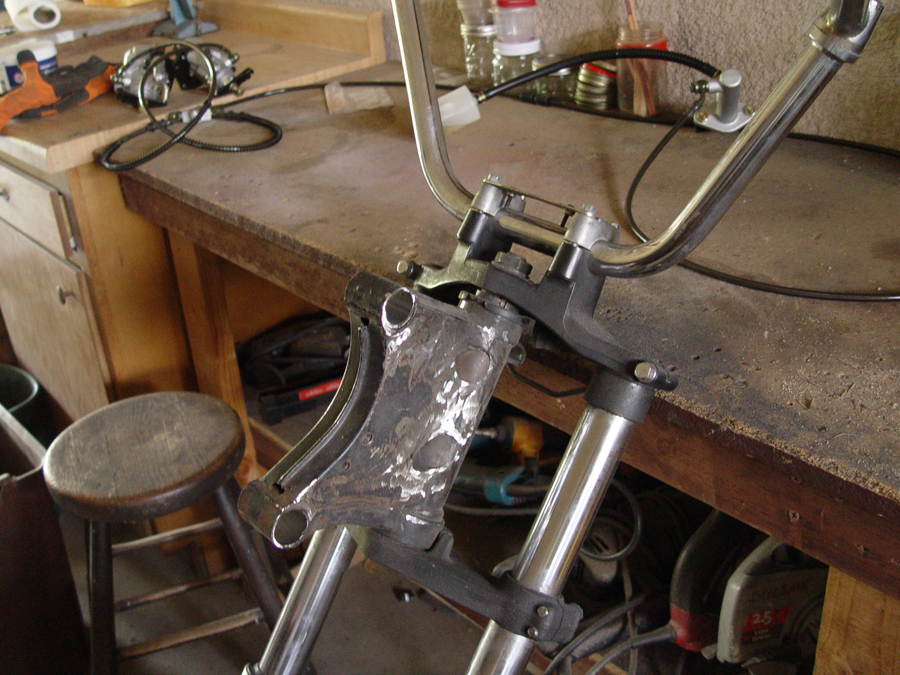
The steering tube and front fork have machined “stops”  (See red arrows in Photo 3)  and a centering pin (See white arrow in Photo 3) which prevent the front wheel and fork from being turned too far left or right thereby creating a dangerous or unstable condition.    By fitting identically sized wooden shims between the center pin and the stops on each side, the fork and the “junction box” can be clamped in place at dead center to insure the junction box, steering head and front wheel will be pointed straight forward when the fork is welded to the frame. (Photo 4)


Photo 5 – Angle supports tack welded in place

Angle supports between the  base frame and junction box can now be tack welded in place. (Photo 5)

Photo 6 – The angle supports are welded to the fork’s “junction box” (arrow)


The arrow in Photo 6 identifies the junction box which is used as the upper  welding point for the angle supports. (22a)


Photo 7 – Front uprights are welded in place

The front uprights (red arrows in Photo 7) are cut and welded to the base frame and the front fork “junction box”.


Photo 8 – Front fork welded to base frame
Photo 9 – Front fork welded to frame

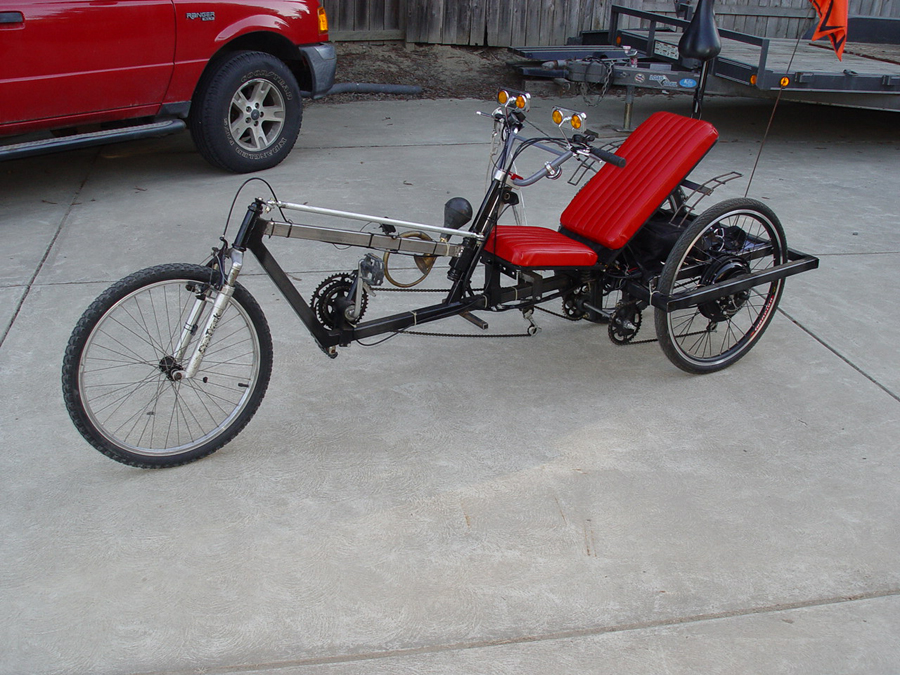
Two more views of the front fork welded to the base frame. (Photos 8 and 9)


Frame Base

Photo 1 – Pieces cut for base frame

The pieces for the base frame are cut from 1x2x.090  wall rectangular steel tubing.  (Photo 1)


Photo 2 – frame notch

A bird’s beak notch is cut into the inside of each rail to make a bend in the  fame.   (Photo 2)


Photo 3 – Preparing to weld frame pieces

Side rails are bent at the notch (see arrows in photo)  and the perimeter pieces of the frame are aligned and clamped together for tack welding.  Note the plumb line used to insure the front, center and rear cross pieces are all on center.   (Photo 3)


Photo 4 – base frame welded

Final welds complete the frame base. (Photo 4)


Donor Motorcycle and Stripping

Photo 1 – 1989 Kawasaki Voyager donor bike

I will be custom fabricating the frame for the trike but many of the basic parts and pieces will come from a donor bike.  For this purpose I purchased a 1989 Kawasaki Voyager 1200 which fit my needs and my budget ($500). The bike was in good running condition and had a clear title and the registration was up to date. So I will be able to use this title as the basis for legally registering the vehicle after the modifications are completed. (See Photo 1)   Note: Please click on any photo for an enlarged version.

The parts I intend to use from the Voyager include:

*Front fork assembly
*Front wheel and tire
*Steering head
*Front dual disc brake assembly including hand controls and hydraulic system
*Seats
*Luggage carrier including adjustable (sliding) base and rack
*Progressive coil over shocks (Series 412 Model 4221)
*Headlight switch and dimmer
*Turn signal switch
*Rear brake pedal assembly
*Horn(s) and horn button
*Rear brake light, turn signal and running lights
*12 volt charger (for my separate 12 lighting system)
*I also intend to use the 97 HP Voyager engine and transmission in a shifter cart project which is next in line after this trike is completed.

The first step of the build process is to totally strip the Kawasaki down and set aside parts and pieces to be used for the trike build. (See Photos 2 and 3)

Photo 2 – Starting to strip down the Kawasaki
Photo 3 – Striping down the Kawasaki


The final major piece to be removed is the motor.   (See Photo 4)

Photo 4 – Removing the engine


The main component I am after on the donor is the front fork/wheel/dual disc brakes assembly.  On the Voyager the front fork is welded directly to the frame.    (See arrow Photo 5)

Photo 5 – Front fork is welded to the frame and must be cut away


The fork must is cut away while saving the main “junction box” which originally connected the frame to the steering head.  (See Photo 6)

Photo 6 – Front fork cut from frame


The “junction box” will serve  as the main welding area for connecting the fork to the new fabricated frame. (See Photos 7 and 8)    By saving the junction box I won’t have to weld directly to the steering head. This  prevents any potential warpage  of the steering head or damage to the VIN plate which is permanently attached to the steering head.


Photo 7 – Front fork showing junction box
Photo 8 – Close up of junction box welded to steering head


Introduction

My goal for this project is to build a commuter vehicle capable of highway speeds (60 mph), a reasonable range (25 miles) and a budget that won’t require a second mortgage ($5K). I have a small bit of experience having built a 500W mid-motor recumbent trike.   (See photo 1).  Details of how that trike was built can be seen here.

Photo 1 – 500W recumbent trike


A year later, wanting a little more power and a little better range, I built a 1000W Yescom USA hub motored trike.   This trike is still ridden daily some three years later and has logged over 4,000 miles. (See photo 2).  Details of how the trike was built can be seen here.


Photo 2 – 1000W recumbent trike


I have also built a number of adaptive bikes and trikes (some electric and some pedal powered) for special needs students at the request of our local Department of Education. All of these trikes have been built using salvaged bicycle components incorporated into custom fabricated frames and new electronics.

These projects have wet my appetite for something bigger, faster, and more utilitarian (grocery getting, running errands, Home Depot jaunts, and local cruising.)    I have chosen to stick with a three wheeled trike design for the following reasons:

a) I am familiar with it from prior builds.
b) It is relatively light weight.
c) It is more stable (for me at age 72) than a two wheel “motorcycle”.
d) It is easier to license here in CA  as a motorcycle than if it were a hand-built four wheel vehicle which would require licensing as a car.
e) although the trike will be  “open air” I am fortunate to live in California’s Central Valley where year-round motorcycle riding is quite common.

The trike will be built using two 3000W, QS Motors hub wheels mounted on the rear. The hubs have 16″ rims, 273 ring size, 40H magnet size and are dual shaft, requiring drop outs on each side of each wheel.   The other major electronic components include:

Two Kelly controllers model KLS7230S (includes regeneration, electronic reverse, and cruise control)
Two controller heat sinks
Cycle Analyst V3 instrument cluster
Dunlop Motorcycle tires (150/80/16)
Kelly 400A72V contactor
Holdwell ED250B-1 emergency shut off
Hydraulic disc brakes on both rear wheels
Dual disc hydraulic brakes on front wheel
Mechanical parking/emergency brake kit
6 – 12 volt EverStart 29DC deep cycle lead acid battery pack rated at 125 amphour.
4 awg welding cable for all main battery wiring.