

Switches for the 12 volt appliances are installed on the “dashboard” panel. The rectangular switch at the top of the array is a three way switch which “shifts the gears” selecting either forward, neutral or reverse. The four round switches are used to turn on the DC/DC converter, to turn on the 12 volt system itself, to control the daytime running lights (headlight and a tail light) and to control nighttime running lights. (Photo 1)
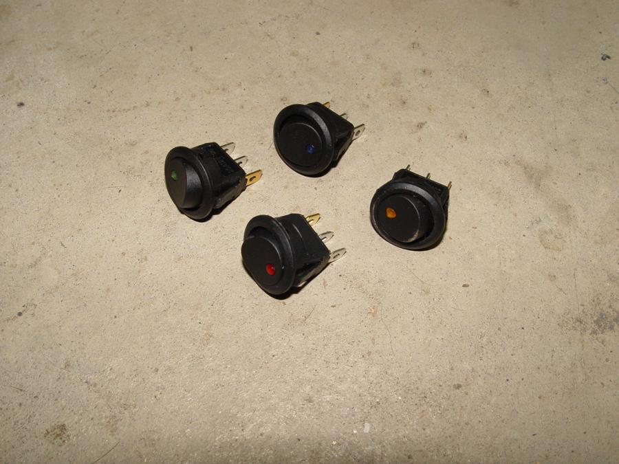
The round switches have small LED lights which indicate when the switch is in the ON position. Each switch LED is a different color to assist during night driving. (Photo 2)

A view of the switches and wiring from under the dash. (Photo 3)

Relays for the turn signals, headlight and running lights are also located under the dash board. (Photo 4)

At the rear of the bike, from bottom to top, are a set of turn signals, a center array which includes the license plate light, brake lights, daytime tail lights and turn signals. Above the center array, in the lower section of the cargo case are the night time tail lights and day/night brake lights. (Photo 5)

At the front of the bike is the headlight which includes internal amber turn signals. To the left and right of the headlight are external turn signals (the pointy arrow like things) (Photo 6)
 Also at the front of the bike is my poor man’s “turn signal cancellation unit”. I have turn signals on by 1,000 watt recumbent and I am forever forgetting to turn them off after making a turn. So on this bike I have mounted turn signals on the handlebars which point rearward rather than forward…right at eye level with the rider. (Photo 7) Not only will these turn signals remind me to cancel the unit, they will actually provide a bit more notification of my turn to anyone traveling behind me, particularly at night. Also in this photo is the center mounted Cycle Analyst 3 which provides a wealth of information regarding the electrical system along with controlling many functions such as the throttle, e-brake cut off, cruise control and high temperature safety shut offs.

I used the Kawasaki donor bike handlebar module for control of the horn, headlight dimmer and turn signals. (Photo 8)

The “magic box” showing the 12 volt system wiring along with the 72 volt wiring. Note that a 12 volt battery is installed as well as a dc/dc converter to provide power to the 12 volt system. Once the bike and electrical systems have been fully road tested, I may remove the auxiliary battery and run only off the converter. (Photo 9)

