
The electric trike will require an emergency brake/parking brake primarily to keep the vehicle from rolling when it is parked and shut off. Unlike a car or motorcycle with a mechanical transmission which can keep the vehicle from rolling when it is parked, the electric trike will roll fairly easily if it is on even a minor grade.
The hydraulic brake system I purchased from QS Motors comes with calipers which have a built in emergency and parking brake mechanism and the system also includes the cables and attachment hardware for operating the system. The kit does not, however, include the parking brake handle or a ratcheting mechanism. In addition a bracket must be fabricated for securing the brake cables to the trike’s frame.
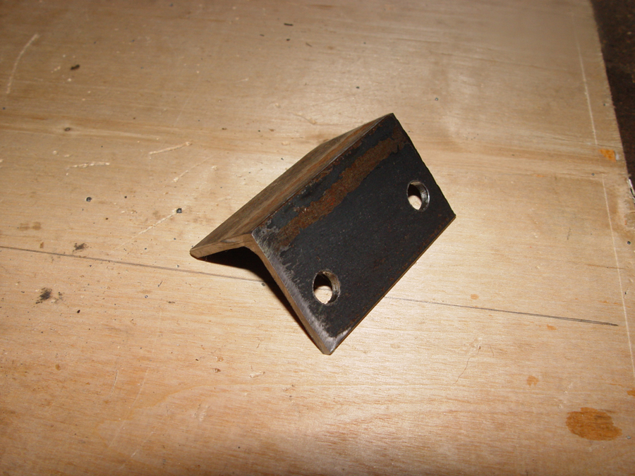
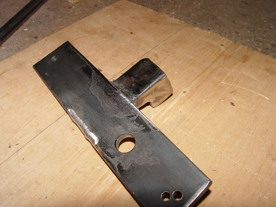
The cable mounting bracket is cut from 1 ½” x 1 ½” angle stock. A hole is drilled to fit the threaded fitting at the end of the brake cable. (Photo 1)
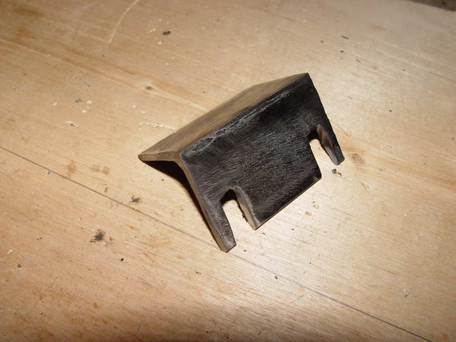
The holes in the bracket are opened up to the outer edge so that the brake cables can easily be installed or removed from the bracket. (Photo 2)
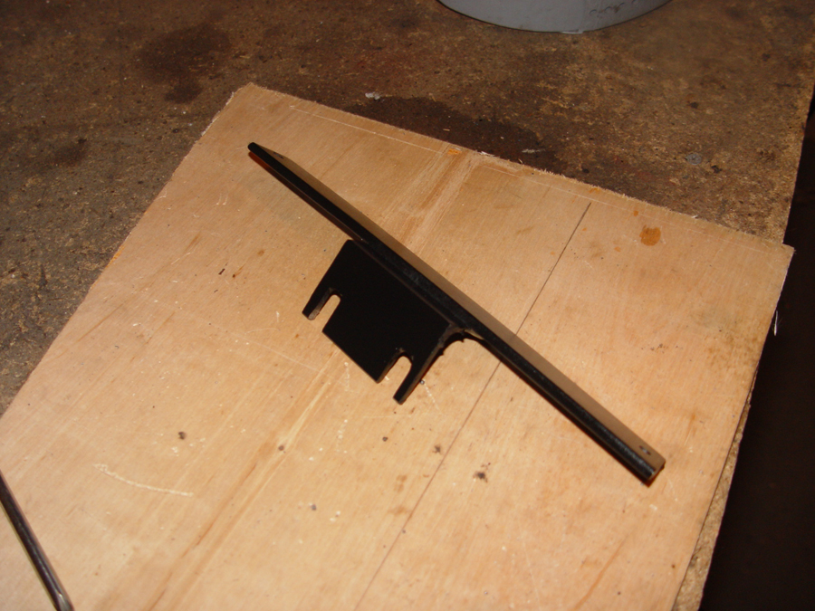
A cross piece is cut from 3/16″ flat stock so that it can fit the width of the frame. The cable mounting bracket is welded to the cross piece. (Photo 3)

The cross piece is bolted to the frame and the cables are secured in the mounting bracket. (Photo 4)

Photo 5 shows the underside of the cables bolted into the mounting bracket.

The brake handle and ratcheting mechanism are an aftermarket unit made to fit a Volkswagon Beatle. These brake handles are primarily used in baja bug type builds and can be purchased for $25-$30. (Photo 6)

A mounting bracket for the brake handle is cut from 3/16″ flat stock and drilled for the mounting bolt. The holes on each end of the bracket are for bolting it to the trike’s frame. (Photo 7)
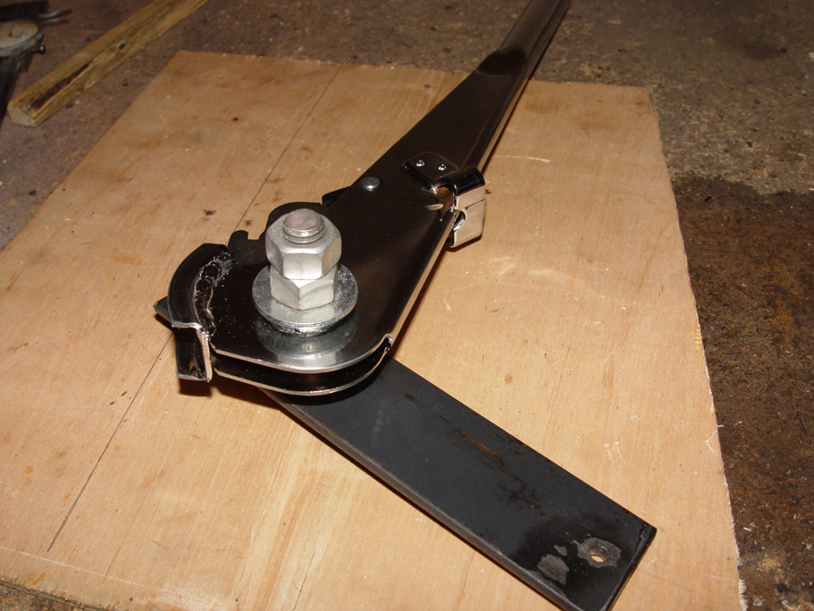
Photo 8 shows the brake handle bolted to the mounting bar.

The only drawback to using the Baja bug brake handle is that the ratcheting mechanism is not held stationary by the handle itself. Instead, the slot shown at the red arrow in Photo 9 normally hooks to a tab on the Volkswagon driveshaft tunnel and this tab holds the ratcheting mechanism in a fixed position. So a stop must be fabricated to keep the ratchet fixed.

The stop is cut from angle iron so that it fits the slot but will not interfere with brake lever as it is engaged or released. (Photo 10)
The stop is positioned and then welded to the brake lever mounting bar. (Photo 11)

Photo 12 shows the brake lever bolted to the mounting bar and the ratchet stop (red arrow)

Photo 13 shows the entire brake lever mechanism and stop bolted onto the trike’s frame. The red arrow shows the ratchet stop.
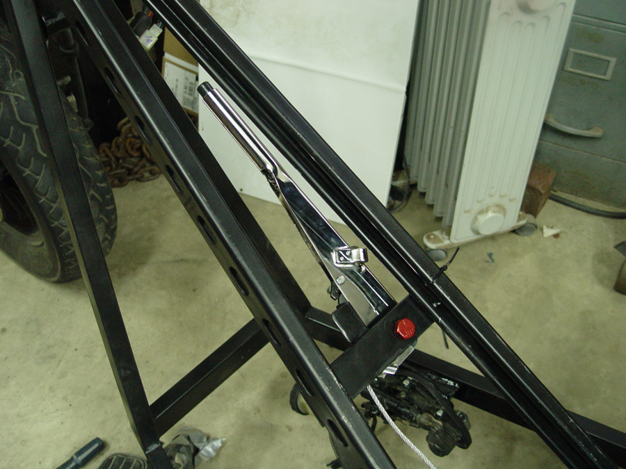
Photo 14 shows the brake lever in the released position. In this position it will be tucked under the “dash” of the trike and partially hidden from view once the dash is installed.
 Photo 15 shows the brake lever in the engaged position. When engaged the level protrudes out from under the dash and will be easy to spot to remind the rider to release before engaging the motor.

